
Elevate Your Networking Expertise by Understanding How Every Layer Shapes the System
Transform complexity into mastery as you shape efficient, resilient network systems.
First Listen: let your ears lead the way before your mind takes notes.
📻 FZ2CCNA Radio:
Then read: let your eyes explore before your mind starts to explain.
Understanding the Role, Components, and Architecture of Routers
Routers are at the core of all inter-network communication. A great way to visualize them is to imagine a central postal hub in a digital city. Every device—PCs, servers, phones—acts like a neighborhood with homes, and each home has an address (an IP address). The router ensures every letter (packet) reaches the correct destination, selecting the right path and applying rules as needed.
In this chapter, we break down what routers are, how they’re built, how they think, and how they forward traffic. By the end, this should feel as intuitive as watching a postal sorting center in action.
I. Routing Roles
Routers direct traffic between networks. Imagine you’re in a big city and trying to drive to a friend’s house. You look at street signs, check your GPS, and follow the best route to get there.
A router does something very similar — but instead of helping cars move around a city, it helps data move around the network.
When people say “routers direct traffic,” they mean that routers:
- Look at where data needs to go: Every piece of data on a network (called a packet) has a destination address, just like a letter has a mailing address.
- Choose the best path to get it there: The router checks its map (routing table) to decide which direction is the best next step. This is like choosing the fastest road on a GPS.
- Send the data toward its destination: Once the router knows the correct direction, it forwards the packet out the right connection (interface) so it can continue its journey.
If your computer wants to visit google.com, the router:
- Sees the destination IP address
- Decides which network to send the packet to
- Sends it toward the internet
Without the router, your packet would have no idea how to leave your home network.
Note: Google does not have a single IP address, but a vast network of addresses that can be used for different services. For Google Public DNS, the IPv4 addresses are (8.8.8.8) and (8.8.4.4). To find the IP address for a specific Google service like google.com, you can use the ping or nslookup command in your command prompt.
Routers direct traffic by looking at where each packet needs to go, choosing the best path, and sending it in the right direction — just like a GPS for your data.
Routers Connect Multiple Networks
Routers exist to connect separate Layer 3 networks by operating at the network layer of the OSI model, where logical addressing and path selection occur.
Each router interface belongs to a different IP network, allowing the router to recognize and separate distinct broadcast domains.
When a packet arrives, the router examines its destination IP address and consults its routing table to determine the appropriate next hop. By forwarding packets between networks with different address spaces, routers enable inter-network communication, enforce segmentation, and support policies such as NAT, ACLs, and QoS. Without routers, communication between independent IP networks would not be possible.
For example:
- Your LAN (home network)
- Your ISP’s network
- The global internet
Each network is its own city. Without a router, none of these cities could communicate.
CCNA Fundamentals:
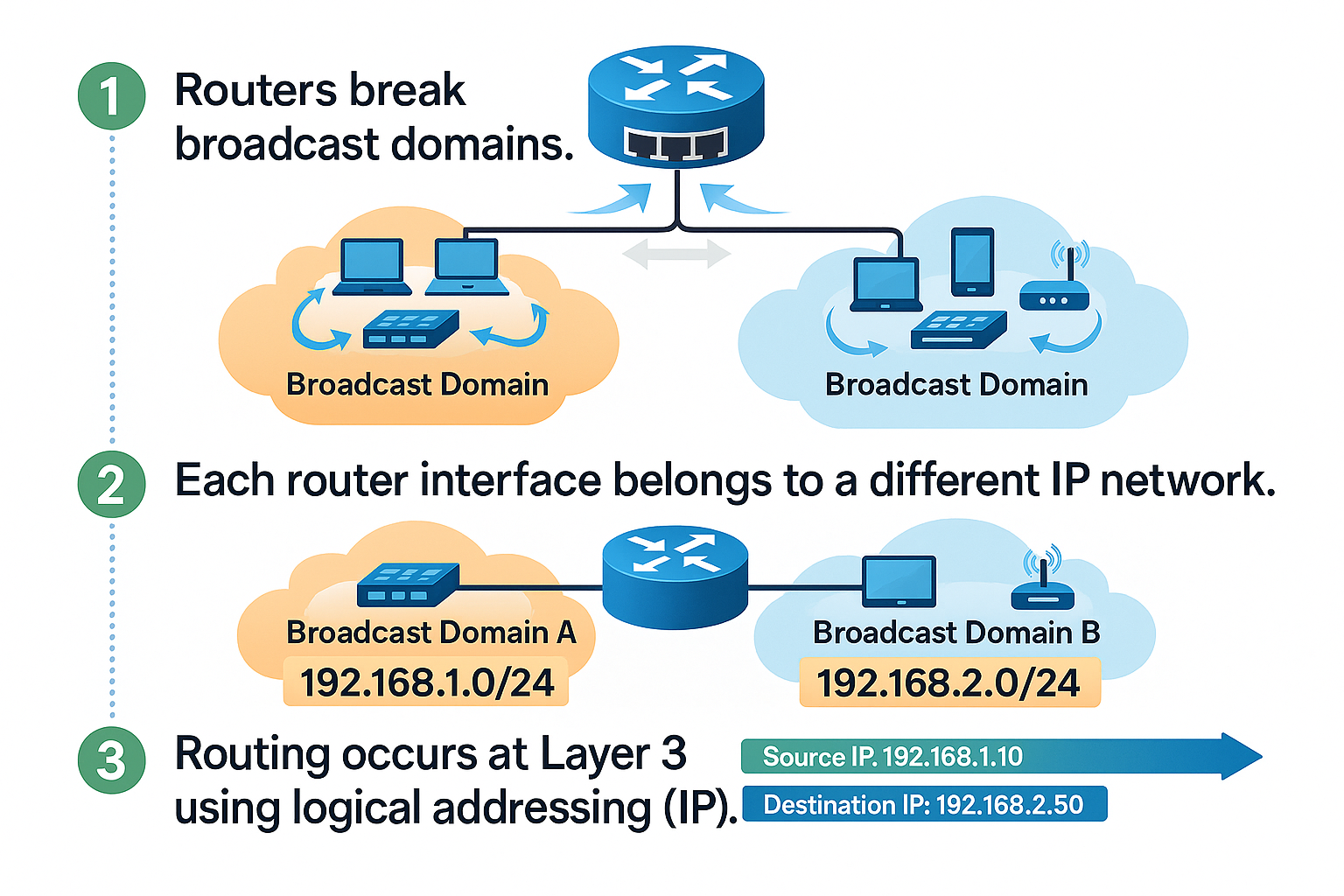
- Routers break broadcast domains.
- Each router interface belongs to a different IP network.
- Routing occurs at Layer 3 using logical addressing (IP).
Routers Determine the Best Path
Routers use routing protocols to learn multiple paths and then choose the most efficient one. When we talk about networking, one of the most important jobs a router has is to determine the best path.
What Does Best Path Mean?
In a network, there are often many possible routes to reach the same destination.
A router’s job is to look at all those possible routes and pick the best one.
You hand a letter to a postal center (the router).
There may be 3 different highways that can reach the same city.
The postal center must decide:
- Which highway is faster?
- Which is shorter?
- Which avoids traffic congestion?
- Which is more reliable?
- The chosen highway is the best path.
How Do Routers Learn About These Paths?
Routers learn routes in three ways:
1. Directly Connected Networks
Just like a postal center already knows the street around its own building.
2. Static Routes
These are like manual instructions given to the postal center:
Always send letters for this city using Highway A.
3. Dynamic Routing Protocols
These are like postal centers talking to each other and sharing road information:
Highway B is closed today.
Highway C is faster this morning.
Examples of routing protocols:
- RIP
- OSPF
- EIGRP
(CCNA favorites!) …. Don’t worry about this now, we’ll look at it in detail later.
Just keep this in mind: These protocols help routers update their knowledge continuously.
Criteria for Router Path Selection
Routers do not choose randomly. They look at specific metrics, depending on the routing protocol.
Common metrics (decision factors):
- Hop Count: How many routers must the packet pass through?
- Bandwidth: How fast is the path?
- Delay: How long does the transmission take?
- Cost: A calculated value representing path “quality.”
- Hop count = How many postal centers your letter must pass through.
- Bandwidth = How wide and fast the highway is.
- Delay = Expected travel time on that road.
- Cost = The system’s overall rating of route efficiency.
What Happens After the Best Path Is Chosen?
The router installs the best path into its routing table.
The routing table is like a map of the best roads. Every entry says:
If you want to reach this network, use this interface and follow this next hop.
After this, the router can forward packets efficiently.
Putting It All Together
Here is exactly how a router determines the best path:
- Learn routes
- Connected
- Static
- Dynamic
- Compare Administrative Distance
- Trust the most reliable source.
- Compare Metrics
- Install the best path into the routing table.
- Forward packets using the selected path.
This entire process happens in milliseconds.
Remember
Routers must choose the best path to send data.
The decision is similar to a postal center choosing the best road for a delivery.
Routing protocols help routers learn routes.
Metrics guide the decision.
Administrative Distance determines which source is most trustworthy.
The routing table stores only the best routes—not all possible routes.
Segments Broadcast Domains
Switches extend a LAN; routers divide them.
A router stops Layer 2 broadcasts, preventing unnecessary network noise.
This improves:
- Network scalability
- Performance
- Security
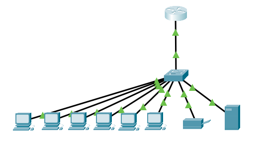
In Ethernet networks, a broadcast domain represents the set of devices that receive broadcast traffic from each other.
Understanding how to control broadcast domains is essential for designing efficient, stable, and secure networks.
What Is a Broadcast Domain?
A broadcast domain is the group of devices that receive Layer 2 broadcast frames sent by any device inside that group.
Broadcasts are used for functions such as:
- ARP requests
- DHCP discovery
- Some network discovery mechanisms
When any device sends a broadcast, every device in the broadcast domain must:
- Accept the frame
- Process it at the CPU
- Discard it if it is not needed
This consumes time, CPU cycles, and network bandwidth.
Why Broadcast Domains Must Be Controlled
Broadcasts are necessary, but they can create problems if allowed to grow unchecked.
Before
After
High traffic levels
- If you place many devices in a single broadcast domain, every broadcast is duplicated and sent to all of them. This increases traffic and slows communication.
Lower device performance
- Each device must process the broadcast and decide whether to respond. Even powerful devices lose efficiency when the broadcast traffic volume increases.
Stability risks
Large broadcast domains are more vulnerable to:
- Broadcast storms
- Misconfigurations
- Faulty NICs creating excessive broadcasts
Security limitations
- Devices in the same broadcast domain see more of each other’s traffic, which increases risk.
- For these reasons, modern networks aim to divide broadcast domains into smaller, manageable portions.
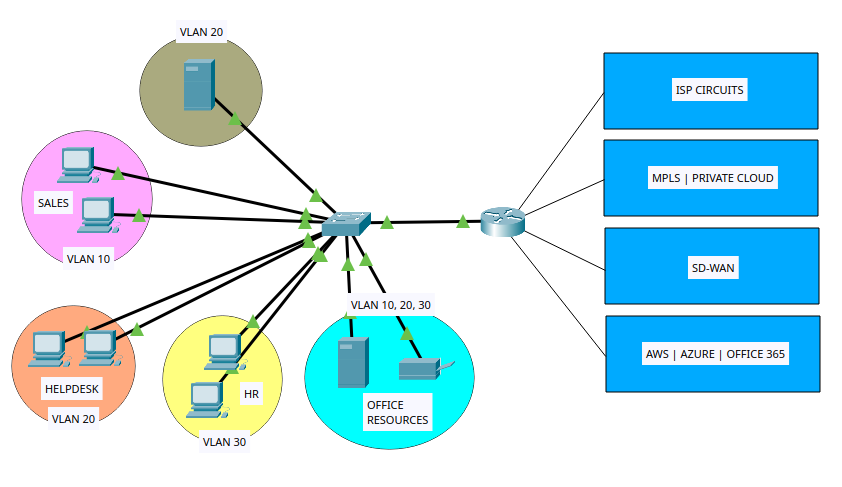
Routers Enable WAN Connectivity
Routers connect LANs to distant networks over:
- ISP circuits
- MPLS
- SD-WAN
- Cloud providers (AWS, Azure)
Remember:
LAN = local
WAN = long-distance “roads”
Routers Support Network Policies (Security, QoS, NAT)
Routers enforce important rules, including:
- ACLs → Filter traffic
- QoS → Prioritize voice/video
- NAT/PAT → Translate private ↔ public IPs
A router does more than just send packets from one network to another.
It also applies rules that control how traffic moves, what traffic is allowed, and how the network behaves.
Routers allow or block traffic (ACLs)
Routers use rules called ACLs to decide:
- Which packets can pass
- Which packets must be blocked
Example: Allow only web traffic. Block everything else.
Routers choose the best path
Routers follow rules to decide which route a packet should take.
They choose paths based on:
- Speed
- Cost
- Policies from the network admin
Example: Use the fastest link unless it is down.
Routers translate addresses (NAT)
Routers can change IP addresses using NAT rules:
- Many devices share one public IP
- Some ports are forwarded to internal devices
Example: Send traffic on port 80 to the web server inside the network.
Routers prioritize traffic (QoS)
Routers can give some traffic higher priority.
Example: Voice calls go first. Downloads wait if needed.
Routers protect the network (Security rules)
Routers may include firewall or VPN rules:
- Block attacks
- Allow only trusted connections
- Secure tunnels for remote users
Example: Only employees can access the internal network via VPN.
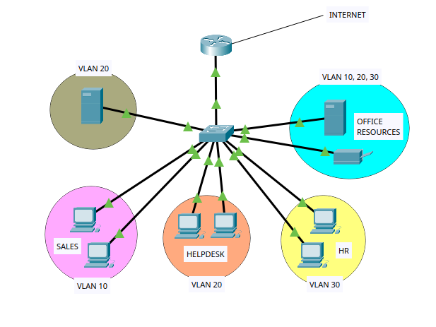
Routers control communication between segments
Routers set rules for which networks or VLANs can talk to each other.
Example: VLAN 10 can reach VLAN 20, but VLAN 30 cannot.
II. Router Components
Routers forward packets between different networks, make path decisions, run routing protocols, and enforce security and filtering rules. To perform these functions, a router depends on several internal hardware and software components, each with a specific purpose. Understanding these components is a foundational requirement for CCNA.
Overview of Major Router Components
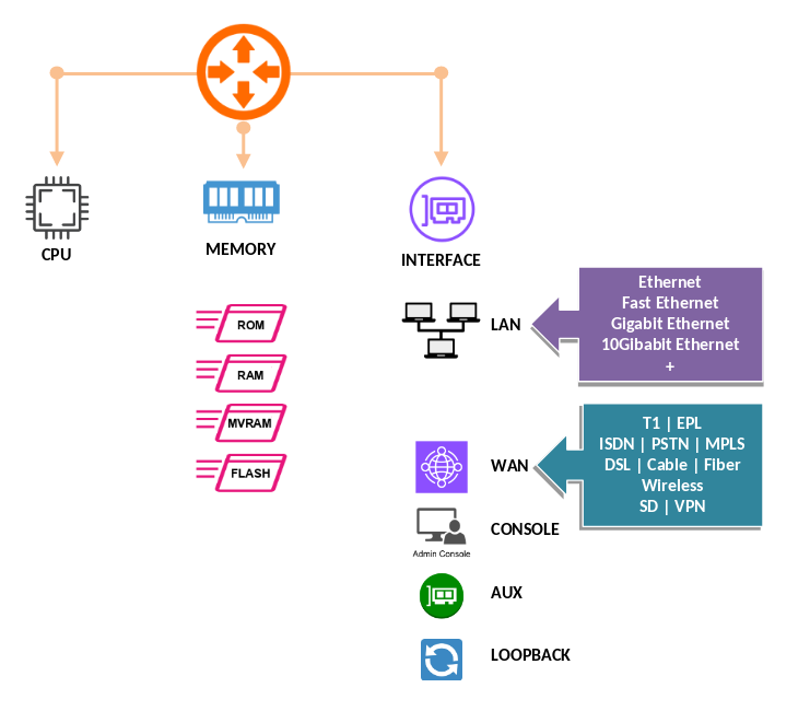
A router contains the following key components:
- CPU (Processor)
- RAM (Random Access Memory)
- ROM (Read-Only Memory)
- NVRAM (Non-Volatile RAM)
- Flash Memory
- Internal Buses / Backplane
- Interfaces (LAN/WAN ports)
- Power Supplies
- Operating System (IOS)
- Configuration Files
CPU (Central Processing Unit)
- The CPU is the main processor of the router. It executes the instructions that control routing operations.
Tasks performed by the CPU:
- Executes the Cisco IOS software
- Builds the routing table
- Computes routing protocol updates
- Handles packet switching processes
- Manages interrupts, queues, cache, and background tasks
The CPU works closely with all memory types and relies on IOS to perform routing decisions.
Router Memory Types
- Cisco routers use multiple types of memory, each with a distinct purpose.
- This is one of the most testable topics in CCNA.
RAM (Random Access Memory)
- RAM is the router’s main working memory. It is volatile, meaning its contents are lost when the router powers off.
RAM stores:
- Running configuration
- Routing tables
- ARP table
- Packet buffers
- Cisco Express Forwarding (CEF) tables
- Process memory for IOS
Because RAM contains the running configuration, any configuration changes you make in CLI appear here first.
NVRAM (Non-Volatile RAM)
- NVRAM retains its contents even when the router is shut down.
NVRAM stores:
- Startup configuration (startup-config)
This is the file the router loads during boot (unless a different boot option is configured).
Flash Memory
- Flash is non-volatile storage used to hold the router’s system image.
Flash stores:
- Cisco IOS image(s)
- Optional files like backup configs or license files
Flash can hold multiple IOS images if space allows. Flash is not erased on reboot.
ROM (Read-Only Memory)
- ROM contains basic boot and diagnostic software.
ROM includes:
- Bootstrap program (loads IOS)
- ROM Monitor (ROMmon) mode
- Basic IOS version for recovery (sometimes)
ROM cannot normally be modified, although some routers support ROM upgrades by replacing the chip or flashing new firmware.
Internal Buses and Backplane
- Routers contain high-speed internal pathways used for communication between components.
The backplane supports:
- Data transfer between interfaces
- CPU and memory communication
- Hardware switching operations
These buses ensure packets move efficiently across the router’s hardware.
Router Interfaces
- Interfaces allow the router to connect to networks. They can be physical or logical.
Physical Interfaces
- Common physical interfaces include:
Ethernet Interfaces:
- FastEthernet (100 Mbps)
- GigabitEthernet (1 Gbps)
- 10-Gigabit Ethernet (10 Gbps)
WAN Interfaces:
- Serial ports
- DSL
- T1/E1
- Fiber interfaces
Each interface has its own bandwidth, duplex setting, MAC address (for Ethernet), and link parameters.
Logical Interfaces
Examples include:
- Loopback interfaces
- Subinterfaces
- SVIs (on multilayer switches)
Logical interfaces are used for routing protocols, testing, and management.
Cisco IOS Software
- The Cisco IOS (Internetwork Operating System) is the router’s operating system.
IOS responsibilities:
- Controls routing protocols
- Manages interfaces
- Enforces security policies
- Provides CLI command structure
- Handles management functions
Different IOS versions support different features.
Configuration Files
- Routers use two main configuration files:
Running Configuration
- Stored in RAM
- Reflects the router’s current, active settings
- Lost on reboot unless saved
View running-config:
show running-configStartup Configuration
- Stored in NVRAM
- Loaded during boot
- Must be manually updated using:
copy running-config startup-configThe Boot Process
When a router powers on, it follows this sequence:
- POST (Power On Self Test)
- Bootstrap program (from ROM) loads
- Bootstrap locates and loads IOS image from Flash
- IOS loads into RAM
- Router loads the Startup configuration from NVRAM
- If no startup-config exists, router enters setup mode
This is a frequent exam topic.
Basic Commands for Viewing Router Components
View memory information
show memory
show version
show flash:
show startup-config
show running-config
View interfaces
show ip interface brief
show interfaces
View IOS version
show versionView boot settings
show bootExample Basic Router Configuration
Below is a small example configuration showing interface setup and saving configuration:
enable
configure terminal
hostname R1
interface GigabitEthernet0/0
 ip address 192.168.10.1 255.255.255.0
 no shutdown
exit
interface GigabitEthernet0/1
 ip address 10.0.0.1 255.255.255.252
 no shutdown
exit
banner motd ^C Unauthorized access prohibited ^C
end
copy running-config startup-config
Summary of Each Memory Type
| Memory Type | Volatile? | Stores | Loaded to |
|---|---|---|---|
| RAM | Yes | Running-config, routing tables, ARP, buffers, IOS runtime | Active processes |
| NVRAM | No | Startup-config | RAM during boot |
| Flash | No | IOS image, files | RAM during boot |
| ROM | No | Bootstrap, ROMmon, basic IOS | Used during boot |
Things to Memorize
- Running configuration is in RAM.
- Startup configuration is in NVRAM.
- IOS image is in Flash.
- Bootstrap and ROMmon are in ROM.
- Commands:
copy running-config startup-configshow flash:show versionshow ip interface brief
- Boot sequence order: POST → Bootstrap → IOS → Startup-config
Exam Tips
- Expect questions that compare the memory types directly.
- Be prepared to identify where IOS is stored and where it runs.
- Be comfortable with
show versionoutput. - Know what happens if IOS is missing (router goes to ROMmon).
- Understand that losing power erases RAM but not Flash or NVRAM.
- Remember that the router boots from Flash by default unless changed by
boot systemcommands.
Router components include the CPU, multiple memory types, interfaces, internal buses, and the Cisco IOS software. RAM holds the active configuration and routing information; NVRAM holds the startup configuration; Flash holds the IOS; ROM contains the bootstrap program. Interfaces provide the router's physical and logical connections to networks. Understanding these components is essential for both daily network operations and CCNA exam success.
III. Router Architecture
A router is a specialized device designed to forward packets between networks. To do this, it must perform route selection, switching, encapsulation, buffering, and security processing. Its architecture defines how all the internal components work together—hardware, software, data paths, memory systems, interfaces, and operating processes.
Understanding router architecture is essential because it influences performance, scalability, and the router’s behavior during forwarding and routing protocol operations. This chapter explains router architecture gradually and clearly.
High-Level View of Router Architecture
Most routers follow a structured design that includes:
- Control Plane
- Data Plane (Forwarding Plane)
- Management Plane
- CPU
- Memory Systems (RAM, NVRAM, Flash, ROM)
- Hardware Switching ASICs (in modern routers)
- Interface Modules
- Internal Buses / Backplane
- Cisco IOS or IOS-XE
These pieces form a unified architecture that allows the router to accept packets, analyze them, and forward them efficiently.
The Control Plane
The control plane is the decision-making component of a router. It is responsible for building the information used by the data plane.
The control plane handles:
- Running routing protocols (OSPF, EIGRP, BGP, etc.)
- Building the routing table (RIB — Routing Information Base)
- Managing neighbor relationships
- Processing network events
- Handling protocols such as ARP, ICMP, CDP, LLDP
All of these tasks run on the CPU, using normal system processing cycles.
Control plane outputs:
- Routing Table (RIB)
- CEF Table / FIB (Forwarding Information Base)
- Adjacency Table
The router uses the control plane’s calculations to prepare the data plane for fast forwarding.
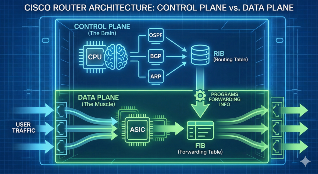
The Data Plane (Forwarding Plane)
The data plane is responsible for actual packet forwarding. It uses precomputed tables created by the control plane.
Data plane tasks:
- Forwarding packets at line rate
- Applying ACLs
- QoS classification and marking
- NAT translations
- Encapsulation/decapsulation
- Policing and shaping
In older routers, most data-plane tasks were CPU-driven, which made them slower. Modern routers use hardware components such as ASICs and NPUs (Network Processing Units) to forward packets extremely quickly.
Data plane components include:
- FIB (Forwarding Information Base)
- Adjacency Table
- Hardware switching engines (ASICs)
- Interface hardware
This separation of planes is core to modern router design.
The Management Plane
The management plane handles administrative access.
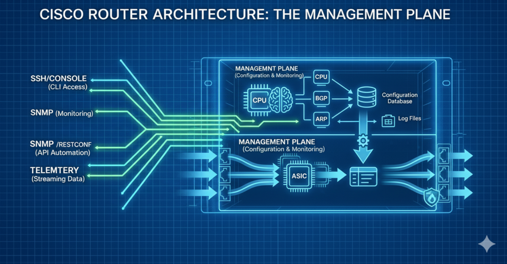
Examples of management-plane functions:
- SSH / Telnet
- HTTP / HTTPS (for GUI tools)
- SNMP
- SYSLOG
- Configuration backups
- Monitoring and statistics collection
Protection of the management plane is critical for security.
Routing Information Flow (Architecture Perspective)
Understanding how routing decisions flow through architecture is essential.
The flow:
- Routing protocols exchange updates.
- Control plane processes routes and builds the RIB.
- RIB is used to build the FIB (CEF table).
- Data plane uses the FIB to forward packets.
- Interface drivers handle final encapsulation and transmission.
This separation allows routers to forward traffic even under heavy CPU load, because the data plane is not dependent on control-plane cycles.
Cisco Express Forwarding (CEF)
CEF is the modern Cisco forwarding architecture. It replaced older methods like fast switching and process switching.
CEF Components:
- FIB — optimized version of the routing table
- Adjacency Table — next-hop layer-2 information
CEF is precomputed and works independently of the CPU. ASICs read entries directly from hardware tables, allowing forwarding at extremely high speeds.
CEF enables:
- Deterministic forwarding
- High performance
- Scalability
CEF is usually enabled by default.
Check CEF status:
show ip cefInternal Router Hardware Architecture
A router contains several physical components that enable packet movement.
CPU
Handles all control-plane tasks.
- Executes IOS
- Manages processes
- Builds routing tables
- Handles interrupts and system timers
Memory Components
Routers use multiple memory types, each with a specific architectural role.
| Memory Type | Function |
|---|---|
| RAM | Running config, routing table, buffers |
| NVRAM | Startup config |
| Flash | IOS image storage |
| ROM | Bootstrap and ROMmon |
Interface Modules
Interface cards allow the router to connect to various networks.
Examples:
- GigabitEthernet modules
- 10GE fiber modules
- Serial WAN modules
- 4G/5G LTE modules
Each module contains:
- Physical transceivers
- Buffers
- ASICs
- Drivers
Backplane / System Bus
The backplane interconnects internal components.
Responsibilities:
- Transfers packets between interfaces
- Connects CPU to memory
- Connects interface modules to forwarding engines
High-end routers use switch fabrics for extremely high throughput.
ASICs and NPUs
Modern routers use hardware engines for data-plane tasks.
ASIC features:
- Very high-speed forwarding
- Low latency
- Deterministic performance
NPUs provide more programmability while remaining hardware accelerated.
Router Software Architecture
Cisco routers run IOS or IOS-XE.
IOS features:
- Monolithic architecture
- Single image loads into RAM
- All functions contained in one OS
IOS-XE features:
- Modular architecture
- Linux-based kernel
- Processes run independently
- More stable and scalable
IOS Processes include:
- Routing daemons
- Management processes
- CEF engine
- Interface drivers
- Security engines
You can view IOS processes using:
show processes cpuThe Boot Architecture
Routers follow a predictable boot sequence.
Boot steps:
- POST (hardware check)
- Bootstrap loads from ROM
- Bootstrap loads IOS from Flash
- IOS loads into RAM
- IOS loads the startup-config from NVRAM
- Router becomes operational
If IOS is missing, the router enters ROMmon.
View boot info:
show bootPacket-Forwarding Architecture
This section explains packet movement inside the router.
Steps:
- Packet arrives on an interface.
- Interface hardware performs Layer 1 and Layer 2 validation.
- Data plane checks CEF table for destination prefix.
- FIB determines the outgoing interface.
- Adjacency table provides Layer 2 encapsulation details.
- Packet is placed in output queue.
- Interface transmits packet.
This architecture ensures high-speed forwarding.
Queueing and Buffer Architecture
Routers use queues to handle congestion.
Key queue types:
- Input queues
- Output queues
- Hardware queues
- Software queues
Buffer roles:
- Store packets temporarily
- Prevent packet loss during bursts
- Support QoS shaping and policing
Monitor queues with:
show interfaces
show queueing
Example CLI Configuration for Forwarding and Interfaces
Below is a simple example of enabling interfaces and verifying CEF behavior.
Enable an interface and assign an IP:
configure terminal
interface GigabitEthernet0/0
 ip address 192.168.1.1 255.255.255.0
 no shutdown
exit
Verify CEF:
show ip cef
show ip cef 192.168.1.0
show adjacency
Verify route installation:
show ip routeThings to Memorize for the CCNA Exam
- Control plane builds the RIB; data plane uses the FIB.
- CEF = FIB + adjacency table.
- IOS is stored in Flash, runs in RAM.
- Startup-config is stored in NVRAM.
- Packet forwarding uses ASICs in modern routers.
- Routing protocols operate in the control plane.
- CEF enables high-performance forwarding.
- Routers have management, control, and data planes.
Exam Tips
- Expect exam questions comparing control plane vs data plane roles.
- Know what CEF is and why it’s faster than fast switching.
- Understand how interface buffers and queues work conceptually.
- Be ready to identify where each table (RIB/FIB/Adjacency) is used.
- Expect questions about where IOS lives before and after boot.
- Memorize the boot sequence thoroughly.
- Understand differences between IOS and IOS-XE (basic level).
- Be prepared for troubleshooting questions involving ROMmon.
Router architecture is a combination of hardware and software systems designed to forward packets efficiently and reliably. The control plane runs routing protocols and builds the RIB; the data plane uses CEF to forward packets rapidly; the management plane supports administrative access. The router’s CPU, memory systems, ASICs, interfaces, and IOS work together to provide stable, high-performance routing. Mastering router architecture gives you a strong foundation for configuration, troubleshooting, and CCNA certification success.
What Did You Learn Today?
Let’s Find Out!
Instructions
- Select the correct answer for each technology concept.
- All questions pertain directly to the networking technologies explained.
- After answering, click “See Result” to see your score and feedback.
Grab the Lab and Test Your Skills
Documentation and topology (for this lab) — click here
[Return to CCNA Study Hub] — Next Stop: [Section 2 | Path Optimization]