
Lab ID: CCNA-RT-W01-L1-RouterBasics-PT-v1
Objective
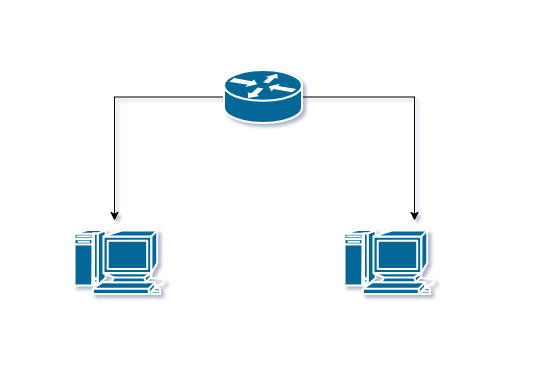
You are given two PCs located in different networks. Your task is to configure the network so that both PCs can communicate through a router. You must also identify key router components using IOS show commands.
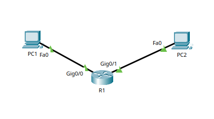
Lab Topology
The lab topology displays information about the network devices in the lab.
Key Commands
| Command | Purpose / What It Does |
|---|---|
enable | Enters privileged EXEC mode (allows advanced commands). |
configure terminal | Enters global configuration mode to modify device settings. |
end | Exits configuration mode and returns to privileged EXEC mode. |
exit | Leaves the current mode or interface context. |
interface <type>/<number> | Enters interface configuration mode for the specified port. |
ip address <address> <mask> | Assigns an IPv4 address and subnet mask to an interface. |
no shutdown | Activates (brings up) an interface that is administratively down. |
show ip interface brief | Displays a summary of interface IP addresses and up/down status. |
show interfaces | Shows detailed information about interface status, hardware, errors, and statistics. |
show running-config | Displays the device’s active configuration stored in RAM. |
show startup-config | Displays the saved configuration stored in NVRAM. |
show ip route | Shows the routing table, including connected and local routes. |
show version | Displays hardware/memory details, IOS version, uptime, and ROM/Flash info. |
ping <address> | Tests connectivity to another device using ICMP echo requests. |
ip route <network> <mask> <next-hop> (optional) | Creates a static route to a destination network. |
The IP addresses and subset masks used in this lab are shown in the tables below:
IP Addresses
| Device | Interface | IP Address | Subnet Mask | Default Gateway |
|---|---|---|---|---|
| PC1 | NIC | 192.168.10.10 | 255.255.255.0 | 192.168.10.1 |
| PC2 | NIC | 192.168.20.10 | 255.255.255.0 | 192.168.20.1 |
| Router | g0/0 | 192.168.10.1/24 | — | — |
| Router | g0/1 | 192.168.20.1/24 | — | — |
Challenge Tasks
Task 1 — Build the Physical Topology
Create the following topology using Packet Tracer:
- PC1 must connect to router interface g0/0
- PC2 must connect to router interface g0/1
- Use appropriate copper cables
- Ensure all physical links are active
Solution
Task 2 — Configure End Devices
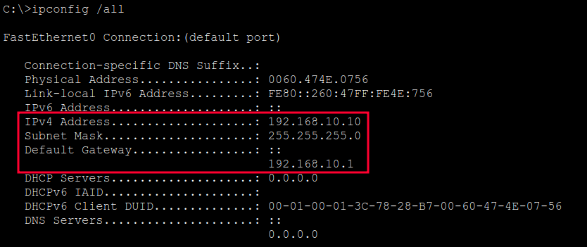
Assign IP addressing to each PC according to the table:
- PC1 → 192.168.10.10 /24, gateway 192.168.10.1
- PC2 → 192.168.20.10 /24, gateway 192.168.20.1
Record your settings and confirm they match the addressing plan exactly.
Solution
PC1
PC2
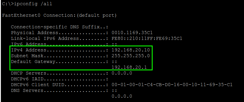
Task 3 — Configure Router Interfaces
Configure the router interfaces with the following requirements:
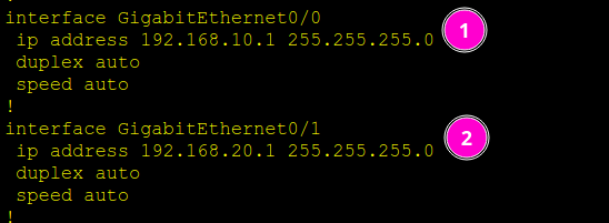
- g0/0 must use IP 192.168.10.1 /24
- g0/1 must use IP 192.168.20.1 /24
- Both interfaces must be operational (administratively up)
- Use “hostname” command to rename Router to R1
No additional routing configuration is required in this lab.
Solution
- Access the router CLI and enter privileged EXEC mode:
enable
- Enter global configuration mode:
configure terminalhostname R1
- Configure g0/0 with the correct IP address and bring the interface up:
interface g0/0ip address 192.168.10.1 255.255.255.0no shutdown
- Configure g0/1 with the correct IP address and bring the interface up:
interface g0/1ip address 192.168.20.1 255.255.255.0no shutdown
- Exit back to privileged EXEC mode:
end
Task 4 — View Device Configuration
Inspect and record:
- The active configuration currently in memory
- The configuration stored in persistent memory
Solution
- Display the running configuration:
show running-config
- Display the startup configuration:
show startup-config
Task 5 — Validate Interface Status
Verify and document:
- Operational status (up/down) of all router interfaces
- IP addressing applied to each interface
Solution
- Check the operational status of all interfaces:
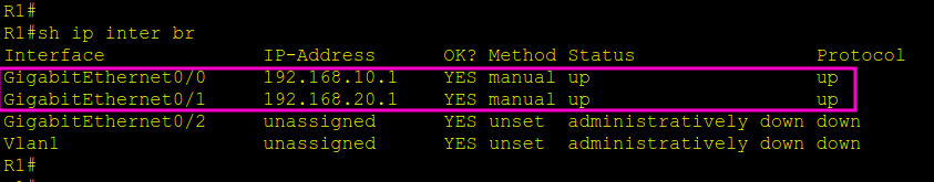
show ip interface brief
- Verify:
- g0/0 is up/up with IP 192.168.10.1
- g0/1 is up/up with IP 192.168.20.1
- For deeper inspection, run:
show interfaces g0/0show interfaces g0/1
Task 6 — Verify Routing Behavior
Examine the router’s routing table and confirm that:
- Both LAN networks appear as connected routes
- Interface IPs appear as local routes
- No static or dynamic routes appear unless intentionally configured
Record your findings.
Solution
- On the router, view the routing table:
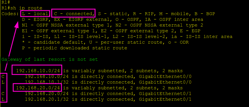
show ip route
- Verify entries for:
- 192.168.10.0/24 (connected)
- 192.168.20.0/24 (connected)
- Local routes for both router interface addresses
Task 7 — Test End-to-End Connectivity
Test communication between devices:
- From PC1, test reachability to PC2 (192.168.20.10)
- From PC2, test reachability to PC1 (192.168.10.10)
If connectivity fails, identify which layer is causing the issue and correct it.
Solution
ping 192.168.20.10ping 192.168.10.10
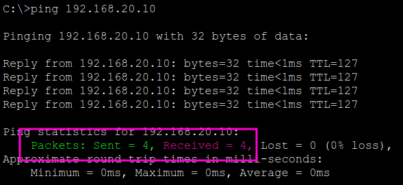
- If pings fail, troubleshoot:
- Interface status
- IP configuration
- Cabling
- Router interface shutdown status
Task 8 — Functional Validation
You have completed the challenge successfully when:
- Both PCs can communicate with each other
- Router interfaces are up with correct addressing
- Routing table displays correct connected networks
- No misconfigurations exist in IP assignments or cabling
Document all your verification results.
Keep Practicing!
This activity is part of the From Zero To CCNA learning path. fromzerotoccna.com