
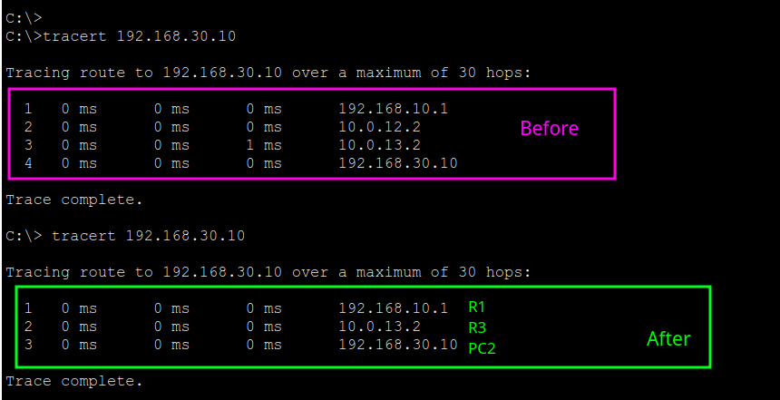
In this lab, your job is to verify the Routing Table and Path Selection
With this topology you have two possible paths between PC1’s network (192.168.10.0/24) and PC2’s network (192.168.30.0/24):
- Direct path: R1 → R3
- Alternate path: R1 → R2 → R3
Your mission is to prove which path the network is using and why, by always checking two things:
- Which route the router selected
- Which path the traffic actually took
IP ADDRESS
| Device | Interface / NIC | IP Address | Subnet Mask | Default Gateway |
| PC1 | NIC | 192.168.10.10 | 255.255.255.0 | 192.168.10.1 |
| SW1 | (L2 ports) | N/A | N/A | N/A |
| R1 | G0/2 (to SW1 / right LAN) | 192.168.10.1 | 255.255.255.0 | N/A |
| R1 | G0/0 (to R2) | 10.0.12.1 | 255.255.255.252 | N/A |
| R2 | G0/0 (to R1) | 10.0.12.2 | 255.255.255.252 | N/A |
| R2 | G0/1 (to R3) | 10.0.23.2 | 255.255.255.252 | N/A |
| R1 | G0/1 (to R3) | 10.0.13.1 | 255.255.255.252 | N/A |
| R3 | G0/0 (to R1) | 10.0.13.2 | 255.255.255.252 | N/A |
| R3 | G0/1 (to R2) | 10.0.23.1 | 255.255.255.252 | N/A |
| R3 | G0/2 (to SW2 / left LAN) | 192.168.30.1 | 255.255.255.0 | N/A |
| SW2 | (L2 ports) | N/A | N/A | N/A |
| PC2 | NIC | 192.168.30.10 | 255.255.255.0 | 192.168.30.1 |
| Admin Laptop | Console (serial/USB) | N/A | N/A | N/A |
Topology details
Devices
- 3 Routers: R1 (center), R2 (bottom-left), R3 (bottom-right)
- 2 Switches: SW1 (top-left), SW2 (bottom-right)
- 2 PCs: PC1 on the right LAN, PC2 on the left LAN
- 1 “Admin” laptop connected to R1 with a console cable (light blue). It’s for configuration, not an IP link.
Right LAN (top-left in the drawing, labeled “right LAN”)
- PC1
- IP: 192.168.10.10
- DG (Default Gateway): 192.168.10.1
- SW1
- You can see Fa0/1 toward PC1 (copper)
- You can see Fa0/2 toward the router (copper)
- R1 toward that LAN
- Interface: G0/2
- IP: 192.168.10.1/24
- This is PC1’s default gateway.
Right LAN network: 192.168.10.0/24
Left LAN (bottom-right in the drawing, labeled “left LAN”)
- PC2
- IP: 192.168.30.10
- DG: 192.168.30.1
- SW2
- Fa0/2 toward PC2 (copper)
- Fa0/1 toward the router (copper)
- R3 toward that LAN
- Interface: G0/2
- IP: 192.168.30.1/24
- This is PC2’s default gateway.
Left LAN network: 192.168.30.0/24
Router-to-router links (triangle = alternative paths)
These links are /30 (point-to-point), so they’re perfect for path selection practice:
R1 ↔ R2 (10.0.12.0/30)
- R1 G0/0 = 10.0.12.1/30
- R2 G0/0 = 10.0.12.2/30
R1 ↔ R3 (10.0.13.0/30)
- R1 G0/1 = 10.0.13.1/30
- R3 G0/0 = 10.0.13.2/30
R2 ↔ R3 (10.0.23.0/30)
- R2 G0/1 = 10.0.23.2/30
- R3 G0/1 = 10.0.23.1/30
Router path selection
The key is that between 192.168.10.0/24 and 192.168.30.0/24 you have 2 paths:
- R1 → R3 (direct)
- R1 → R2 → R3 (via R2)
With that you can practice:
- Longest Prefix Match (LPM): /24 beats /16
- Administrative Distance (AD): who wins between static/OSPF/EIGRP
- Metric (OSPF cost / EIGRP metric): which route “costs less”
- ECMP (load-balancing): equal-cost routes
- Failover: what happens when a link goes down
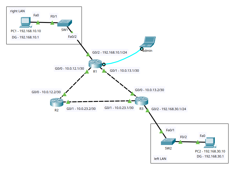
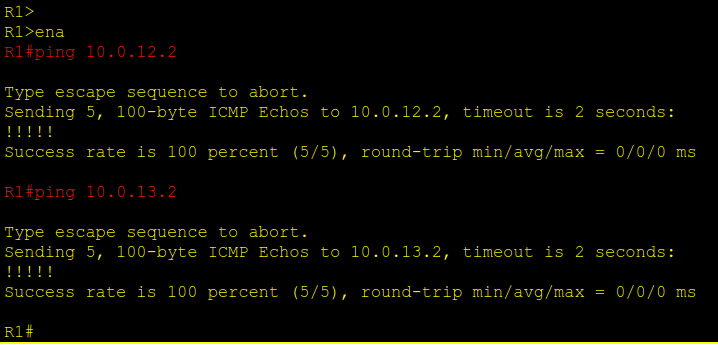
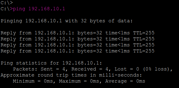
Task (a) — Verify basic Layer 3 connectivity (baseline)
Objective: Confirm all point-to-point links and LAN gateways are reachable before enabling/validating routing behavior.
Steps:
- From R1, verify reachability to directly connected neighbors
ping 10.0.12.2ping 10.0.13.2
- From PC1, verify reachability to its default gateway
ping 192.168.10.1
- From PC2, verify reachability to its default gateway
ping 192.168.30.1
Expected Results:
- All pings should succeed (5/5 replies or equivalent success rate).
Solution
Task (b) — Enable Dynamic Routing: OSPF (metric/cost)
Objective: Confirm OSPF adjacencies form correctly and that OSPF-learned routes are installed, then verify the end-to-end path between LANs.
Verification Steps:
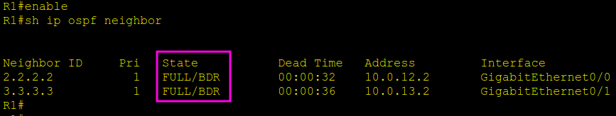
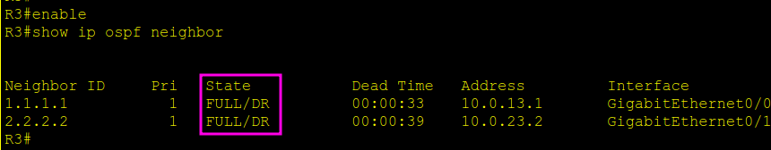
- Verify OSPF neighbor adjacencies: R1, R2 and R3
show ip ospf neighbor
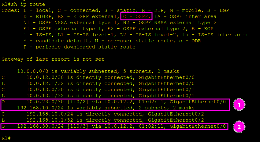
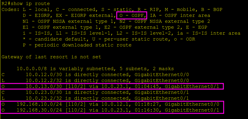
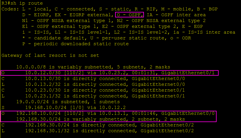
- Verify OSPF routes are present in the routing table: R1, R2 and R3
show ip route ospf
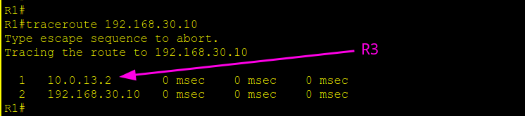
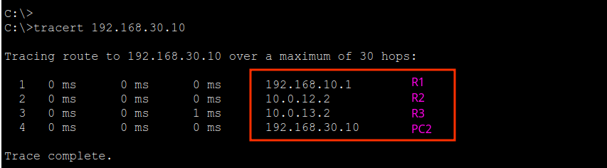
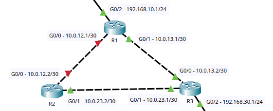
- Verify the end-to-end forwarding path from the PC
- From PC1:
tracert 192.168.30.10
(or runtraceroute 192.168.30.10from a router)
- From PC1:
Expected Results:
- OSPF neighbors should show in the FULL state (adjacencies up).
- The routing table should contain O (OSPF) routes for remote networks.
- Traceroute should successfully reach
192.168.30.10and display the hop-by-hop path (either via R3 directly or via R2 then R3, depending on costs).
Solution

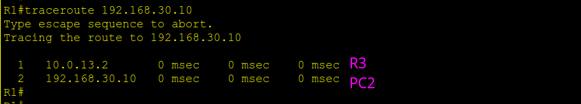
Task (c) — Force an alternate OSPF path (change route selection)
What was done and why:
This configuration was applied on purpose to alter the path selection. By increasing the OSPF cost on R1’s direct link to R3 (G0/1), the direct path R1 → R3 becomes more expensive from an OSPF metric perspective.
Your job is to verify that R1 is no longer using the direct connection to R3, and that it is now being forced to use R2 first, then R3 to reach Host PC2 (192.168.30.10).
Configuration Applied (do not change)
R1 to 192.168.30.0 via R2
On R1, the cost of the direct link to R3 was increased:
R1# conf t
int g0/1
 ip ospf cost 100
end
Your Verification Tasks
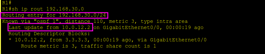
- Confirm the route R1 is installing for 192.168.30.0/24
- On R1:
show ip route 192.168.30.0
The next-hop should point toward R2 (via the R1–R2 link), meaning R1 is choosing the path R1 → R2 → R3. - On R1:
- Confirm the actual forwarding path from PC1 to PC2
- From PC1:
tracert 192.168.30.10
The hops should show traffic going:
R1 → R2 → R3 → PC2 - From PC1:
Expected Result
- The traceroute from PC1 confirms the traffic is taking R1 → R2 → R3 to reach PC2.
- The routing table on R1 shows the selected path is via R2, not the direct link to R3.
Solution
Task (d) Simple fail-over (path change when a link goes down)
Shut down the direct R1–R2 link (gigabitEthernet 0/0) and watch the route change:
Type (R1)
conf
int g0/0
Sh
R1#configure terminal
Enter configuration commands, one per line. End with CNTL/Z.
R1(config)#interface g0/0
R1(config-if)#shutdown
R1(config-if)#
%LINK-5-CHANGED: Interface GigabitEthernet0/0, changed state to administratively down
%LINEPROTO-5-UPDOWN: Line protocol on Interface GigabitEthernet0/0, changed state to down
00:30:17: %OSPF-5-ADJCHG: Process 1, Nbr 2.2.2.2 on GigabitEthernet0/0 from FULL to DOWN, Neighbor Down: Interface down or detached
R1(config-if)#- With OSPF, traffic should re-converge via R1→R3.
- Verify with traceroute and show ip route (R1).
- Verify with tracert 192.168.30.10 (PC1)
Solution
LAB ID: CCNA-Path_Selection-FZ2CCNA-0100-PT