
Lab ID: LABS-PT-20260116-A7K3
Introduction
This lab is not pre-built. Build this entire lab in Packet Tracer. You’re responsible for the full topology and configuration. Prove it works by testing connectivity and validating every requirement. If you haven’t installed it yet or don’t know how to use the simulator, go to: https://fromzerotoccna.com/packet-tracer/
Objective: Create a scenario that covers all the requested topic(s).
Configure two routers so that two LANs can communicate by correctly configuring router interfaces (Ethernet + Serial), enabling/disabling interfaces, and creating loopback interfaces. Then log on to the PCs and verify end-to-end connectivity using ping and router verification commands like show ip interface brief.
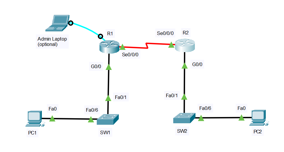
TOPOLOGY
Devices
- 2x Routers: R1, R2
- 2x Switches: SW1, SW2
- 2x PCs: PC1, PC2
Links (with exact ports)
- PC1 NIC ↔ SW1 F0/6
- SW1 F0/1 ↔ R1 G0/0
- R1 S0/0/0 ↔ R2 S0/0/0 (point-to-point serial — Add: The HWIC-2T is a Cisco 2-Port Serial High-Speed WAN Interface Card, providing 2 serial ports.)
- R2 G0/0 ↔ SW2 F0/1
- SW2 F0/6 ↔ PC2 NIC
Segmentation
- No VLAN segmentation in this lab (VLAN: N/A everywhere)
Cable Connections (assume Auto-MDI/MDIX is disabled)
- PC ↔ Switch: Copper straight-through
- Switch ↔ Router (Ethernet): Copper straight-through
- Router ↔ Router (Serial): Serial DCE/DTE cable (one side will be DCE and must provide clocking. Value 64000)
- For initial configuration: Console cable from a Admin laptop to each router/switch (This step is optional—if you want to simulate real field work. Otherwise, just log into each device individually.)
Device Renaming Requirement
- Rename devices to: R1, R2, SW1, SW2, PC1, PC2, Admin laptop (optional)
Command Summary
| Command | Description |
|---|---|
enable | Enter privileged EXEC mode |
configure terminal | Enter global configuration mode |
hostname <name> | Rename the device |
interface g0/0 | Enter GigabitEthernet interface configuration |
interface s0/0/0 | Enter Serial interface configuration |
interface loopback0 | Create/enter loopback interface |
description <text> | Add an interface description |
ip address <ip> <mask> | Assign IPv4 address/mask to an interface |
no shutdown | Administratively enable an interface |
shutdown | Administratively disable an interface |
encapsulation ppp | Set PPP on a serial link |
clock rate 64000 | Set DCE clocking on a serial interface |
ip route <net> <mask> <next-hop> | Configure a static route |
show ip interface brief | Quick interface/IP/status check |
show interfaces serial 0/0/0 | Detailed serial interface status |
show ip route | View routing table |
ping <ip> | Test connectivity |
IP Address Table
| Device | Interface | IP Address | Subnet Mask | Default Gateway | VLAN | Notes |
|---|---|---|---|---|---|---|
| R1 | G0/0 | 192.168.10.1 | 255.255.255.0 | N/A | N/A | LAN1 gateway |
| R1 | S0/0/0 | 10.10.10.1 | 255.255.255.252 | N/A | N/A | Serial to R2 |
| R2 | G0/0 | 192.168.20.1 | 255.255.255.0 | N/A | N/A | LAN2 gateway |
| R2 | S0/0/0 | 10.10.10.2 | 255.255.255.252 | N/A | N/A | Serial to R1 |
| PC1 | NIC | 192.168.10.10 | 255.255.255.0 | 192.168.10.1 | N/A | End host on LAN1 |
| PC2 | NIC | 192.168.20.10 | 255.255.255.0 | 192.168.20.1 | N/A | End host on LAN2 |
Lab Tasks
Task 1: Build, cable, and rename the topology
What you will do: Physically build the topology with correct cable types and rename all devices.
- Place R1, R2, SW1, SW2, PC1, PC2.
- Cable each link using the correct cable type (straight-through vs serial vs console).
- Rename: Routers to R1/R2, switches to SW1/SW2, PCs to PC1/PC2.
Task 2: Configure router physical interfaces (Ethernet + Serial)
What you will do: Address and enable Ethernet and Serial interfaces, add descriptions, and bring links up.
- Rename all devices.
- Prevent DNS lookup delays
- Configure R1 G0/0 and R2 G0/0 with the IPs from the table and
no shutdown. - Configure R1 S0/0/0 and R2 S0/0/0 with the /30 IPs.
- Set PPP encapsulation on both serial interfaces.
- Identify the DCE side and set a
clock rateon the DCE interface (value 64000). - Verify interface states using
show ip interface brief.
Task 3: Configure loopbacks, routing, and test shutdown/no shutdown
What you will do: Create loopbacks, add static routes, verify end-to-end pings, then practice disabling/enabling an interface.
- Configure static routes so LAN1 ↔ LAN2 can communicate. (both side)
- Verify with
ping(PC-to-PC, router-to-loopback). - On R1,
shutdownG0/0, observe impact, thenno shutdownand re-test.
Lab Solution
Task 1 Solution: Build, cable, and rename
Device renaming (Routers)
On the router console (repeat for each router):
enable
configure terminal
no ip domain-lookup
hostname R1
end
copy running-config startup-config
On the second router, use:
enable
configure terminal
no ip domain-lookup
hostname R2
end
copy running-config startup-config
Device renaming (Switches)
On SW1:
enable
configure terminal
hostname SW1
end
copy running-config startup-config
On SW2:
enable
configure terminal
hostname SW2
end
copy running-config startup-config
PC addressing
PC1 (Desktop > IP Configuration)
- IP:
192.168.10.10 - Mask:
255.255.255.0 - Default Gateway:
192.168.10.1
PC2 (Desktop > IP Configuration)
- IP:
192.168.20.10 - Mask:
255.255.255.0 - Default Gateway:
192.168.20.1
Task 2 Solution: Configure router physical interfaces (Ethernet + Serial)
R1 configuration
enable
configure terminal

interface g0/0
 description LAN1 to SW1 F0/1
 ip address 192.168.10.1 255.255.255.0
 no shutdown

interface s0/0/0
 description Serial link to R2 S0/0/0
 ip address 10.10.10.1 255.255.255.252

 encapsulation ppp
 no shutdown
end
write memory
R2 configuration
enable
configure terminal

interface g0/0
 description LAN2 to SW2 F0/1
 ip address 192.168.20.1 255.255.255.0
 no shutdown

interface s0/0/0
 description Serial link to R1 S0/0/0
 ip address 10.10.10.2 255.255.255.252
 encapsulation ppp
 no shutdown
end
write memory
Set clock rate on the DCE side (only one side)
In Packet Tracer, one serial end will be DCE. Try this on R1 first; if it errors, do it on R2.
On the router you suspect is DCE:
enable
configure terminal
interface s0/0/0
clock rate 64000
end
write memory
Verify interfaces
On R1 and R2:
show ip interface brief
show interfaces serial 0/0/0
Success looks like:
- G0/0 is up/up
- S0/0/0 is up/up
Task 3 Solution: Configure loopbacks, routing, and test shutdown/no shutdown
Configure loopback interfaces
Static routing for LAN-to-LAN
On R1 (route to LAN2 via R2 serial IP):
enable
configure terminal
ip route 192.168.20.0 255.255.255.0 10.10.10.2
end
write memory
On R2 (route to LAN1 via R1 serial IP):
enable
configure terminal
ip route 192.168.10.0 255.255.255.0 10.10.10.1
end
write memory
Verification tests
On R1:
show ip route
ping 10.10.10.2
ping 192.168.20.1
On R2:
show ip route
ping 10.10.10.1
ping 192.168.10.1
From PC1:
- Ping PC2:
ping 192.168.20.10
From PC2:
- Ping PC1:
ping 192.168.10.10
Success looks like 100% (or near 100%) ping replies after ARP settles.
Practice shutdown / no shutdown (impact test)
On R1 (disable LAN1 interface):
enable
configure terminal
interface g0/0
shutdown
end
Now from PC1, ping 192.168.20.10 should fail.
Re-enable it:
enable
configure terminal
interface g0/0
no shutdown
end
Re-test from PC1:
ping 192.168.20.10should succeed again.