
Lab ID: LABS-PT-20260128-C10T2
Introduction
This lab is not pre-built. Build this entire lab in Packet Tracer. No templates ——you are responsible for the full topology and configuration. Prove it works by testing connectivity and validating every requirement. If you haven’t installed it yet or don’t know how to use Packet Tracer, go to: https://fromzerotoccna.com/packet-tracer/
Objective
You’re onboarding a small access switch stack and need to identify what’s plugged where without relying on CDP (mixed-vendor environment). You’ll enable LLDP, verify neighbor discovery, and then troubleshoot why one link isn’t showing up in LLDP even though the physical link is up.
Goal: LLDP neighbors appear correctly on the distribution switch, and you can prove interface-to-interface connectivity using LLDP output.
Cable Connections (Required): You MUST use correct cable types (console/rollover, straight-through). Assume Auto-MDI/MDIX is disabled. Device Renaming (Required): Rename devices to SW1, SW2, PC.
TOPOLOGY
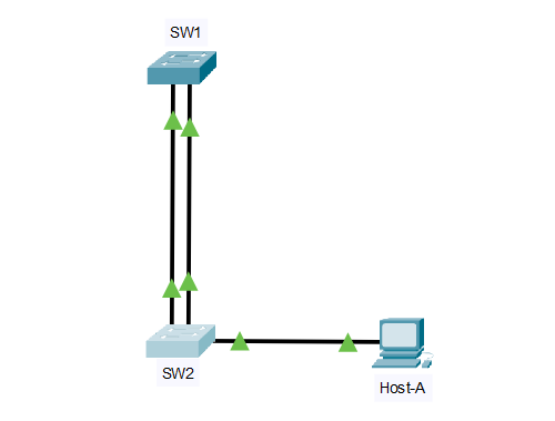
Suggested topology
Devices
- SW1 Cisco 2960
- SW2 Cisco 2960
- PC1 on SW2 (optional, just to generate some traffic)
Links
- SW1 Fa0/1 (link to) SW2 Fa0/1 (Uplink #1)
- SW1 Fa0/2 (link to) SW2 Fa0/2 (Uplink #2)
VLANs
- VLAN 10 = Users
- VLAN 99 = Management (optional; doesn’t matter for LLDP but feels real)
Roles
- SW1: distribution switch aggregating access links
- SW2: access switch with end hosts
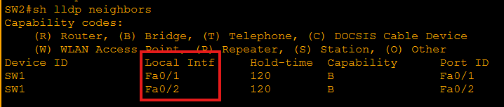
Before Link Aggregation
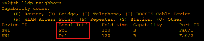
After Link Aggregation
Interface intent
- Fa0/1 and Fa0/2 as trunks (or access—LLDP works either way; trunking just makes it more realistic)
Intentional fault to inject
Fault: LLDP is globally enabled, but LLDP transmit is disabled on one interface on SW2 (or SW1).
Result: The link is up/up and passes traffic, but one neighbor relationship is missing or one-sided in LLDP tables.
Example fault (on SW2):
- interface fa0/2
- no lldp transmit
This is super realistic when someone copies a “security hardening” snippet or tinkers with discovery protocols.
Key verification steps
Run these on both switches
Check LLDP global status
show lldp
show running-config | include lldp
Check LLDP neighbors
show lldp neighbors
show lldp neighbors detail
Check per-interface LLDP state
show lldp interface
show lldp traffic
Confirm physical/link state (so you don’t chase ghosts)
show interfaces status
show interfaces fa0/2 (or relevant port)
What good looks like
- SW1 sees SW2 on both Fa0/1 and Fa0/2
- SW2 sees SW1 on both Fa0/1 and Fa0/2
- show lldp traffic increments over time (TX/RX frames)
Diagnosis and fix
Symptoms you should see
- show interfaces status shows both uplinks connected
- show lldp neighbors shows only one neighbor entry (or one interface missing)
- Or: SW1 sees SW2 on Fa0/2, but SW2 does not see SW1 (one-way discovery)
How to pinpoint the fault
Confirm LLDP is on globally:
show lldpCheck which port is missing:
show lldp neighborsInspect LLDP per-interface state:
show lldp interfaceYou’ll see something like Fa0/2 with TX disabled (or RX disabled)
Fix
On the broken side (example SW2 Fa0/2):
conf t
interface fa0/2
lldp transmit
lldp receive
end
(If you want it super minimal: just remove the no lldp transmit line.)
Re-verify
- show lldp neighbors
- show lldp neighbors detail
- show lldp traffic (TX/RX should climb)
Known-good LLDP outputs
Notes
- LLDP tables can take ~30 seconds to populate/update depending on timers.
- “Port ID” may show as Fa0/1 or an interface ID depending on PT version, but it should clearly map to the neighbor’s uplink port.
SW1
show lldp
SW1# show lldp
Global LLDP Information:
    Status: ACTIVE
    LLDP advertisements are sent every 30 seconds
    LLDP hold time advertised is 120 seconds
    LLDP reinitialization delay is 2 seconds
show lldp neighbors
SW1# show lldp neighbors
Capability codes:
  (R) Router, (B) Bridge, (T) Telephone, (C) DOCSIS Cable Device
  (W) WLAN AP, (P) Repeater, (S) Station, (O) Other

Device ID     Local Intf     Hold-time  Capability  Port ID
SW2           Fa0/1          120        B           Fa0/1
SW2           Fa0/2          120        B           Fa0/2
show lldp neighbors detail (sample for one link)
SW1# show lldp neighbors detail
------------------------------------------------
Chassis id: 0011.2233.4455
Port id: Fa0/1
Port Description: FastEthernet0/1
System Name: SW2
System Description:
Cisco IOS Software, C2960 Software (C2960-LANBASEK9-M), Packet Tracer
Time remaining: 115 seconds
System Capabilities: B
Enabled Capabilities: B
Management Addresses:
    IP: 192.168.99.2
------------------------------------------------
(You should also see a similar block for Local Intf: Fa0/2 / Port id: Fa0/2.)
show lldp interface
SW1# show lldp interface !(this command doesn’t work in Packet Tracer)
LLDP interfaces:

Interface    Tx   Rx   Tx State  Rx State
Fa0/1        yes  yes  enabled   enabled
Fa0/2        yes  yes  enabled   enabled
show lldp traffic
SW1# show lldp traffic
LLDP counters:
    Total frames out: 20
    Total frames in:  20
    Total frames discarded: 0
    Total frames unrecognized: 0
(Counts will vary, but in/out should be increasing over time.)
SW2
show lldp
SW2# show lldp
Global LLDP Information:
    Status: ACTIVE
    LLDP advertisements are sent every 30 seconds
    LLDP hold time advertised is 120 seconds
    LLDP reinitialization delay is 2 seconds
show lldp neighbors
SW2# show lldp neighbors
Capability codes:
  (R) Router, (B) Bridge, (T) Telephone, (C) DOCSIS Cable Device
  (W) WLAN AP, (P) Repeater, (S) Station, (O) Other

Device ID     Local Intf     Hold-time  Capability  Port ID
SW1           Fa0/1          120        B           Fa0/1
SW1           Fa0/2          120        B           Fa0/2
show lldp neighbors detail (sample for one link)
SW2# show lldp neighbors detail
------------------------------------------------
Chassis id: 00aa.bbcc.ddee
Port id: Fa0/1
Port Description: FastEthernet0/1
System Name: SW1
System Capabilities: B
Enabled Capabilities: B
Management Addresses:
    IP: 192.168.99.1
------------------------------------------------
show lldp interface
SW2# show lldp interface
LLDP interfaces:
Interface    Tx   Rx   Tx State  Rx State
Fa0/1        yes  yes  enabled   enabled
Fa0/2        yes  yes  enabled   enabled
show lldp traffic
SW2# show lldp traffic
LLDP counters:
    Total frames out: 18
    Total frames in:  18
    Total frames discarded: 0
    Total frames unrecognized: 0
Quick good vs bad comparison
GOOD
show lldp neighbors shows two entries on each switch (Fa0/1 and Fa0/2)
show lldp interface shows Tx yes / Rx yes on both uplinks
show lldp traffic in/out increases
COMMON “BAD” (your intentional fault)
One-way visibility: SW1 sees SW2 but SW2 doesn’t see SW1 on that link (or vice versa)
One interface missing from show lldp neighbors
show lldp interface shows Tx disabled (or Rx disabled) on the problem port
HOME | Configure and Verify CDP | Lecture CDP & LLDP