
Host-to-Host Communication in TCP/IP
Layers 2 and 3
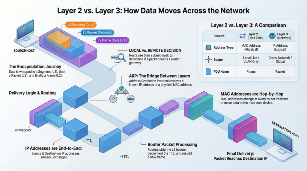
Modern IP networking works because two OSI layers operate together with precision:
- Layer 3 (Network) – decides where the packet must go.
- Layer 2 (Data Link) – decides how to reach the next device on the local link.
Understanding how these two layers cooperate is essential for CCNA-level networking, troubleshooting, and real-world network design.
The Roles of Layer 2 and Layer 3
| Layer 3 | Network | Determines the global path (routing decision) | IP Address | End-to-End |
| Layer 2 | Data Link | Delivers frames to the next hop locally | MAC Address | Local (Hop-by-Hop) |
Key Concept:
IP addresses remain constant from source to destination.
MAC addresses change at every router hop.
Encapsulation
Before data is transmitted, it must be wrapped in layers of control information. This process is called encapsulation.
Step-by-Step Encapsulation
- Application Layer
- Data is created (web page, email, file, etc.).
- Layer 4 – Transport
- Adds TCP or UDP header.
- Includes:
- Source port
- Destination port
- Sequence numbers (TCP)
- Result:
- Segment (TCP)
- Datagram (UDP)
- Layer 3 – Network
- Adds IP header.
- Includes:
- Source IP
- Destination IP
- TTL
- Result: Packet
- Layer 2 – Data Link
- Adds:
- Destination MAC
- Source MAC
- FCS (Frame Check Sequence)
- Result: Frame
- Adds:
- Layer 1 – Physical
- Converts frame to electrical signals or radio waves.
Protocol Data Units (PDUs)
| Layer | PDU | Information Added |
|---|---|---|
| 4 | Segment/Datagram | Port numbers |
| 3 | Packet | IP addresses, TTL |
| 2 | Frame | MAC addresses, FCS |
Layer 2 | Local Delivery (Ethernet)
Layer 2 operates only inside a single broadcast domain (VLAN).
Responsibilities
- Framing
- Physical addressing (MAC)
- Media access control (CSMA/CD or CSMA/CA)
- Error detection (FCS)
Ethernet Frame Structure
Key fields:
- Destination MAC
- Source MAC
- Type
- Payload (IP packet)
- FCS
Ethernet Frame Facts
| Property | Value |
|---|---|
| Minimum size | 64 bytes |
| Maximum size | 1518 bytes |
| MTU | 1500 bytes |
Frames smaller than 64 bytes are called runts.
Frames larger than 1518 bytes are giants (excluding VLAN tag).
MAC Addresses
A MAC address uniquely identifies a NIC.
- Length: 48 bits (6 bytes)
- Format: Hexadecimal (e.g., A1:B2:C3:D4:E5:F6)
- Structure:
- First 24 bits: OUI (vendor)
- Last 24 bits: Unique identifier
Important Rule
MAC addresses identify the next hop, not the final destination across the network.
How Switches Operate
Switches forward frames based on MAC addresses.
The MAC (CAM) Table
A switch stores:
MAC Address — Port — VLANSwitching Logic
- Learning
- Records source MAC and ingress port.
- Forwarding
- Known unicast = sends to specific port.
- Unknown unicast = floods within VLAN.
- Broadcast (FF:FF:FF:FF:FF:FF) = floods.
- Entries age out (default 300 seconds on Cisco).
VLANs | Logical Segmentation
A VLAN creates separate Layer 2 broadcast domains.
- Broadcasts stay within the VLAN.
- Hosts in different VLANs require routing.
Inter-VLAN Communication Methods
- Router-on-a-Stick
- One trunk link to router.
- Router performs routing.
- Layer 3 Switch (SVI)
- Switch performs routing internally.
Local vs Remote Decision
Before sending traffic, a host determines:
Is the destination local or remote?
It performs:
IP address AND Subnet MaskIf:
- Network IDs match = local delivery
- Network IDs differ = send to default gateway
🗝️This is the first critical Layer 3 decision.
Local Communication | Same Subnet
If Host A communicates with Host B in the same subnet:
Process
- Host-A checks ARP cache.
- If MAC not known = sends ARP broadcast.
- Target (Host-B) replies with ARP unicast.
- Host-A builds frame:
- Destination MAC = Host B
- Source MAC = Host A
- IP addresses unchanged
- Switch forwards frame.
- Router not involved.
ARP (IPv4 Only)
- Resolves IP = MAC
- Requests ➡️ are broadcast.
- Replies ⬅️ are unicast.
- Routers ⛔ do not forward ARP broadcasts.
Remote Communication | Different Subnet
If destination is remote:
Process
- Host-A identifies default gateway.
- ARP for gateway MAC (if not known).
- Frame is built:
- Destination MAC = Gateway MAC
- Source MAC = Host MAC
- Destination IP = Final host
- Source IP = Original host
- Switch forwards to router.
Important:
IP addresses remain unchanged.
MAC addresses identify the next hop.
Router Processing
When a router receives the frame:
Step-by-Step
- Verifies destination MAC matches its interface.
- Removes Layer 2 header/trailer.
- Examines destination IP.
- Looks up routing table.
- Decrements TTL.
- Determines outgoing interface.
- Resolves next-hop MAC (ARP/NDP).
- Re-encapsulates with new MAC addresses.
- Sends frame.
What Changes at Each Router?
| Field | Status |
|---|---|
| Source MAC | Changes |
| Destination MAC | Changes |
| Source IP | Same |
| Destination IP | Same |
| TTL | Decreases |
Routing Table Overview
Each route contains:
- Destination network
- Next-hop IP
- Outgoing interface
- Administrative Distance (AD)
- Metric
Common Route Codes
| Code | Meaning |
|---|---|
| C | Connected |
| L | Local |
| S | Static |
| O | OSPF |
| D | EIGRP |
| * | Default route |
Default route:
0.0.0.0/0TTL and ICMP
TTL
- Prevents routing loops.
- Decrements at each router.
- If TTL reaches 0 → packet dropped.
ICMP
Used for control and diagnostics.
Tools
- Ping
- Uses ICMP Echo Request/Reply.
- Traceroute
- Sends packets with increasing TTL.
- Receives ICMP Time Exceeded from routers.
Traffic Types
| Type | MAC | IP | Scope |
|---|---|---|---|
| Unicast | Specific | Specific | One-to-one |
| Broadcast | FF:FF:FF:FF:FF:FF | 255.255.255.255 | Local VLAN |
| Multicast | 01:00:5E… | 224.0.0.0/4 | Group members |
IPv6 and ARP Replacement
IPv6 eliminates ARP.
Neighbor Discovery Protocol (NDP)
- Uses ICMPv6.
- Uses multicast instead of broadcast.
- More efficient than ARP.
CCNA tips
- MAC addresses are hop-by-hop.
- IP addresses are end-to-end.
- Routers rewrite Layer 2 headers.
- TTL decreases at every router.
- ARP only works within a broadcast domain.
- Default gateway handles remote traffic.
- Switches flood unknown unicast traffic.
Summary
When two hosts communicate:
- Data is encapsulated.
- Host checks if destination is local.
- If local = ARP for target MAC.
- If remote = ARP (IPv4 only) for gateway MAC.
- Router strips and rebuilds Layer 2 headers.
- IP addresses remain constant.
- Process repeats at each hop.
- Destination decapsulates data.
Layer 2 delivers locally.
Layer 3 delivers globally.
Both layers must cooperate for communication to succeed.
What Did You Learn Today?
Let’s Find Out!
Grab the Lab and Test Your Skills
Documentation and topology (for Data Forwarding lab) — click here
[Return to CCNA Study Hub] — Next Stop: [Section 2 | End-to-End Packet Delivery] …Available Soon!