
In this section, you will cover the core steps of initial Cisco router configuration needed to bring a device into a stable, operational state. You will start by reviewing the essential baseline components (such as device identification, secure access, and configuration storage). Next, you will move into interface configuration, where physical and logical interfaces are enabled and prepared to carry traffic according to network requirements.
You will then apply IPv4 addressing to router interfaces, ensuring the router can provide Layer 3 connectivity between networks. Finally, you will focus on the importance of interface verification, using standard IOS show and test commands to confirm interface status, addressing, and end-to-end reachability, and to troubleshoot common issues.
Item 5 is a lab activity where you will practice configuring an IPv4 address on router interfaces and verifying the results.
Click on each title to expand its section.
First Listen: let your ears lead the way before your mind takes notes.
📻 FZ2CCNA Radio:
Then read: let your eyes explore before your mind starts to explain.
Initial router configuration is less about memorizing commands and more about following a repeatable, secure workflow. In the real world you rarely get a blank router —sometimes it has partial configs, unknown passwords, leftover VLANs, or mismatched interface settings. A good process helps you take control of the device, confirm what you’re working with, lock down access, build connectivity, enable management, and prove everything works. Basically, this is the whole process:
- Getting In: You need local access, usually connecting your laptop via the console port.
- Power On: Watch it boot up…
- (Power-On Self-Test (POST)
- Loads the operating system (IOS)
- Loads the config.
- The Blank Slate: If there’s no saved configuration, you’ll hit the dreaded “setup dialog.”
- The Basics: Put in a minimal, secure configuration (like a hostname, passwords, an IP address on an interface, and then save everything!).
- Check It Out: Use your show commands to verify the status.
Remember, since routers don't have a screen and keyboard, you always use a PC to connect, and for the initial setup, you connect directly to the console port.
Console Connections (RJ-45 vs. USB)
Your console port might be an RJ-45 or a USB port. The cable you use is often called a rollover cable.
- RJ-45 Console: Takes the standard RJ-45 plug. The PC side usually has a DB-9 serial connector or sometimes a USB connector (or you use a USB adapter). If your cable is DB-9 and your laptop is modern (USB only), you’ll absolutely need a serial-to-USB adapter and the right driver for it.
- USB Console: Just needs a standard USB cable (like Type-A to mini-B) and the corresponding driver for your OS (macOS, Windows or Linux).
Pro Tip: If your router has both an RJ-45 and a USB console port, only one is active at a time:
- Plug in the USB console, and the RJ-45 console stops working.
- Unplug the USB console, and the RJ-45 console comes back online.
This is a very frequent cause for the sudden failure of console access.
Terminal Emulator Settings (Memorize These!)
To chat with the router over the console, fire up an app like PuTTY or Tera Term and use these exact settings—seriously, memorize them:
- Speed (baud): 9600
- Data bits: 8
- Parity: None
- Stop bits: 1
- Flow control: None
If you get junk characters, a blank screen, or weird intermittent output, check your COM/TTY port selection, make sure the driver is installed (especially for USB), and double-check those baud rate and flow control settings.
The Router Boot Process (What’s Happening Inside)
When you power up, the router does three main things:
- POST: Runs self-diagnostics on the CPU, memory, and interfaces.
- IOS Load: Finds and loads the Cisco operating system image.
- Config Load: Looks for and loads the saved configuration file (if one exists).
Make sure your cables are good and the console is connected before you power on so you can watch the magic happen.
Where the Config Lives
After POST and the IOS loads, the router checks NVRAM for the startup-config file.
- If it exists: It loads the config, and you get the Router> prompt.
- If it’s missing: It kicks you into the initial configuration routine, a.k.a. “setup.”
The Setup Dialog: How to Skip It
If the startup-config is missing, you’ll see the System Configuration Dialog:
....System Configuration Dialog....
Continue with configuration dialog? [yes/no]:
CCNA Quick Facts:
- Setup is a prompted guide for a minimal configuration.
- It’s not for complex features; you should always use the CLI for that.
- Its purpose is a fast way to get a basic config when there’s nothing saved.
How to Skip and Use the CLI
To manually configure, exit the setup dialog.
- Answer the first question with no, or
- Just hit Ctrl-C.
You can always start it manually later with the setup command from privileged EXEC mode.
IOS Command Modes (The CLI Path)
In the real world and CCNA labs, you almost always configure manually using the CLI modes:
- User EXEC: Router> (Limited checks)
- Privileged EXEC: Router# (Full monitoring + access to config modes)
- Global Configuration: Router(config)# (Device-wide stuff)
- Sub-modes: Router(config-if)# (Interface), Router(config-line)# (Console/VTY)
The typical way in:
Router> enable
Router# configure terminal
Router(config)#
A Solid Baseline Configuration (Must-Do Steps)
A straightforward and conventional configuration approach is presented here.
Step 1 — Name It
configure terminal
hostname R1
Step 2 — Secure Admin Access
enable secret Str0ngEnableSecretStep 3 — Secure Console Access
line console 0
password C0nsoleP@ss
Login
exec-timeout 10 0 (Timeout after 10 min 0 sec)
logging synchronous (So your typing doesn't get messed up by system messages)
Exit
Step 4 — Secure Remote Access (SSH is best practice)
To enable SSH:
ip domain-name lab.local
crypto key generate rsa modulus 2048
username admin privilege 15 secret Adm1nP@ss
line vty 0 4
login local
transport input ssh
Exit
Step 5 — Hide the Weak Passwords
service password-encryptionStep 6 — Set Interface IP and Turn It On
interface gigabitEthernet0/0
description LAN
ip address 192.168.1.1 255.255.255.0
no shutdown (This turns the interface on!)
Exit
Step 7 — SAVE YOUR WORK (Don’t forget this!)
copy running-config startup-configThe Logic: running-config is what's active now. startup-config (in NVRAM) is what loads on the next boot. You have to copy the running to the startup config!8) Verification Commands (Quick Checks)
Check these right away:
- show version (Platform, IOS version, uptime, and image)
- show running-config (The current active configuration in RAM)
- show ip interface brief (Super quick way to see IP, status, and protocol)
- show startup-config (Confirm your config was actually saved)
Why This Matters in the Real World
These skills are essential for:
- Swapping out a failed router.
- Fixing a remote access issue (SSH/Telnet broken) by using the console.
- Making sure the device won’t lose its config on a reload (copy run start discipline!).
- Troubleshooting why a router is asking you to go into “setup” mode (missing config!).
CCNA Exam Quick Tips
Common Test Points:
Console Settings: 9600 8N1, no flow control.
Boot Order: 1) POST. 2) Load IOS. 3) Load config.
Setup Trigger: No startup-config found in NVRAM.
Skip Setup: Answer no or press Ctrl-C.
Quick Summary
You initially connect with a PC using a console cable and a terminal emulator set to 9600 8N1 with no flow control. When it boots, it does POST, loads the IOS, then loads the startup-config from NVRAM. If the config is gone, it hits the setup dialog, which you should skip with no or Ctrl-C to configure manually. After setting up the basics, confirm everything with show version and show running-config, and then save your config.
What Did You Learn Today?
Let’s Find Out!
Instructions
- Select the correct answer for each technology concept.
- All questions pertain directly to the networking technologies explained.
- After answering, click “See Result” to see your score and feedback.
Grab the Lab and Test Your Skills
Documentation and topology (for this lab) — click here
Setting Up Router Ports
What configuring a port really means
📻 FZ2CCNA Radio:
A router’s primary function is to forward Layer 3 IP packets from one network to another. However, when a router boots, its physical and logical interfaces are not automatically usable for production forwarding because the device does not have enough operational parameters to participate correctly at Layer 1 (physical), Layer 2 (data link), and Layer 3 (network) on each port.
In practice, each router interface is an independent forwarding endpoint that must be explicitly defined so the router can:
- Bring up the link (Layer 1): establish a valid physical carrier and operational state (for example, link negotiation on Ethernet, or clocking and signaling on serial).
- Operate with the correct data-link behavior (Layer 2): know how to format and interpret frames on that medium (for example, Ethernet framing on LAN ports, or PPP/HDLC encapsulation on serial WAN links), including parameters that influence link protocol status.
- Participate in IP forwarding (Layer 3): understand what IP network exists on that interface by assigning an IPv4/IPv6 address and mask/prefix, which creates a connected route in the routing table and defines the interface as a valid ingress/egress point for routed traffic.
Because of this, the router cannot guess how you intend to use a port. You must configure the key per-interface items that determine forwarding behavior, such as:
- Administrative state: enabling the interface (no shutdown) so it can transition from administratively down to an operational state.
- Layer 3 addressing: IPv4 address + subnet mask (or IPv6 address/prefix) so the router can identify the directly connected subnet and perform routing decisions.
- Encapsulation / link settings (when applicable): the correct Layer 2 protocol and any required parameters (common on WAN/serial links, trunks, tunneling, etc.).
- Role-specific settings: features that change how the port forwards (examples: VLAN subinterfaces, trunking on router-on-a-stick, NAT inside/outside designation, ACL application, HSRP/VRRP, QoS, MTU adjustments).
Only after these critical interface parameters are defined can the router reliably accept traffic on an ingress interface, perform a routing table lookup, apply relevant policies (ACL/NAT/QoS), and forward the packet out the correct egress interface.
Some of the typical things you set up are:
- Port description (like a nickname)
- IP address
- The way data is packaged (encapsulation)
- The kind of cable/media
- Speed (Bandwidth)
- Clock rate (mostly for older links)
- Any special features for that specific port
These details matter because the port is where the router connects to the physical cable (Layer 1), handles the data frame (Layer 2), and often uses the IP address (Layer 3).
- Question: Why is configuring a router interface important in terms of the OSI model layers (Layer 1, Layer 2, and Layer 3)?
- Answer: Because the interface connects to the physical cable (Layer 1), processes frames (Layer 2), and uses IP addressing to route packets (Layer 3).
Main physical port types on Cisco routers
This guide focuses on the two main physical connection types for moving packets:
- Ethernet ports
- Serial ports
Ethernet ports
Ethernet is a big family name. The specific name Cisco IOS uses depends on the speed it supports:
- interface Ethernet … (the old, slow 10 Mbps)
- interface FastEthernet … (100 Mbps)
- interface GigabitEthernet … (1 Gbps)
- interface TenGigabitEthernet … (10 Gbps)
- interface TwentyFiveGigE … (25 Gbps)
- interface FortyGigabitEthernet … (40 Gbps)
- interface HundredGigE … (100 Gbps)
Tip for the CCNA: You should be able to read the name and instantly know the technology and the typical speed.
Serial ports
Serial ports are used for older, classic wide area network (WAN) setups like dedicated leased lines and older Frame Relay connections. You usually pick and set up a Layer 2 protocol like:
- HDLC
- PPP
- (or Frame Relay for those specific connections)
You still configure the port in IOS using:
- interface serial interface-identifier
Port names
Routers often have a bunch of the same type of port, so Cisco uses interface-identifiers to tell them apart. The format changes based on the router hardware:
- Port number (e.g., interface ethernet 1)
- Slot/port (e.g., interface fastethernet 0/1)
- Module/slot/port (e.g., interface serial 1/0/1)
Quick Note: On modular routers, slot and module are the actual physical places where the cards are plugged in. On fixed routers, the numbers are still important but are just internal references to the hardware layout.Loopback ports (virtual, super-reliable connections)
A loopback interface is a virtual port that only exists in the router’s software. It’s not physically connected to anything.
Here’s why they’re great:
- A loopback port won’t ever go down unless:
- the router itself crashes, or
- you manually turn it off
Because they are so stable, loopbacks are often used for management access and as reliable identifiers in routing setups. This guide points out that loopbacks are great for management because you’ll always have at least one active port on the router (the loopback).Creating a loopback and giving it an IPv4 address
Example from the guide:
Router(config)# interface loopback0
Router(config-if)# ip address 10.0.0.1 255.255.255.255
This is a host IPv4 address (mask 255.255.255.255, which is /32). -> /32 is the common mask for loopbacks.
Important detail (also noted): you can use a less specific mask on a loopback (like /24). If you do that, the routing table sees it as a connected network, but for many IOS features, the address is still treated as a /32 host route.The On/Off Switch: shutdownand no shutdown
This is a frequently tested CCNA topic:
- When you first set up a physical port, you must turn it on administratively before the router can send and receive packets on it.
- Use no shutdown to turn a port on.
- Use shutdown to turn a port off (administratively disabled).
- Use no shutdown again to turn it back on.
Why would you turn a port off?
- Hardware maintenance
- Separating a broken network segment from the rest of the network
Example: turning on an Ethernet port
Router1# configure terminal
Router1(config)# interface GigabitEthernet 0/0
Router1(config-if)# no shutdown
You’ll typically see system messages showing the link and line protocol coming “up.”
Example: turning off a serial port
Router1# configure terminal
Router1(config)# interface Serial 0/0/0
Router1(config-if)# shutdown
You usually see messages showing “administratively down” and “line protocol down.
A common, step-by-step setup process
Step 1: Find the right port
Start by checking what ports you have and their current status:
show ip interface briefYou’re looking for:
- the exact port name (e.g., GigabitEthernet0/0)
- the current IP address (if any)
- The Status/Protocol fields (a quick health check)
Step 2: Get into global configuration mode
configure terminalStep 3: Go into the specific port configuration
interface GigabitEthernet 0/0 Your identifier might be 0/1, 0/0/0, etc., depending on your device.
Step 4: Add a description
description Link to LAN-SW1Descriptions are listed as one of the key things to set up for a port.
Step 5: Set the Layer 3 IP address
ip address 192.168.10.1 255.255.255.0The IP address is another core port detail in the guide’s list.
Step 6: Configure encapsulation (if necessary)
For serial leased lines, you need to choose the correct data-link protocol (usually HDLC or PPP). The exact commands vary. For PPP, you’d typically use encapsulation ppp under the serial interface.
Step 7: Administratively turn the port on
no shutdownYou must do this in most cases for the port to actually pass traffic.
Step 8: Check your work
Common verification commands:
show ip interface brief
show interfaces GigabitEthernet 0/0
show running-config interface GigabitEthernet 0/0
Focusing upon:
- Is the IP address correct?
- Is the admin state “not shut”?
- Is the operational state “line protocol up”?
- Are there any errors (CRC, drops, speed/duplex problems on Ethernet)?
Troubleshooting Port Status
While the guide clearly shows the system messages for “up” and “administratively down,” the main CCNA skill is figuring out the port status quickly:
- Administratively down: Someone used the shutdown command (Fix: use no shutdown).
- Up/down patterns: The physical cable is connected, but the Layer 2 negotiation/framing is probably wrong (a common issue with mismatched encapsulation on serial links, or Ethernet speed/duplex mismatches).
- Down/down: A physical problem, bad cable, the device on the other end is off, or the port hardware is broken.
Stuff to keep in mind for the test. Make sure you know these cold, as they come up directly in test questions:
- The two main physical port types on Cisco routers:
- Ethernet
- Serial
- Port naming is based on speed:
- Ethernet/FastEthernet
- GigabitEthernet
- TenGigabitEthernet
- TwentyFiveGigE
- FortyGigabitEthernet
- HundredGigE
- Serial ports might use HDLC or PPP for leased lines; Frame Relay for Frame Relay setups
- Port identifiers can be number, slot/interface, or module/slot/interface
- Loopback port facts:
- Virtual, no cable needed
- Stays up unless the router is off or you manually turn it off
- Usually addressed with a /32 (255.255.255.255) mask
- Administrative control:
- shutdown turns a port off
- no shutdown turns a port on (or back on)
Exam tips
- If a port isn’t passing traffic, always check if it’s administratively enabled. The guide strongly emphasizes that you must use no shutdown for ports to work.
- If a question asks which port “never goes down unless the router goes down,” the answer is loopback (this exact concept is in the review section).
- Get really good at reading port names and identifiers (especially things like 0/0, 0/1, 1/0/1). The exam often uses confusing naming to hide simple questions.
- For WAN serial questions, remember that picking the correct encapsulation (HDLC vs PPP) is a classic reason for the “link up but protocol issues” state.
Summary
To get your router ports ready to forward packets, you have to set up all the key characteristics (like the description, IP address, encapsulation, speed, etc.) and make absolutely sure the port is administratively enabled. Cisco routers typically use Ethernet or Serial ports, each with its own naming style and setup commands. Loopback ports are virtual and very reliable, often using a /32 address, and are commonly used for management and routing design because they stay “up” unless the router fails or they are manually shut down. Finally, the shutdown and no shutdown commands are critical for the administrative control that decides whether a port can actually move traffic.
What Did You Learn Today?
Let’s Find Out!
Instructions
- Select the correct answer for each technology concept.
- All questions pertain directly to the networking technologies explained.
- After answering, click “See Result” to see your score and feedback.
Grab the Lab and Test Your Skills
Documentation and topology (for this lab) — click here
Configuring an IPv4 address and subnet mask on a Cisco router interface makes that interface a Layer 3 endpoint tied to a specific IP subnet. IOS then installs the connected (C) and local (L) routes, allowing the router to send/receive IPv4 traffic on that link and forward packets between networks using the routing table. The interface must also be enabled (no shutdown) to operate. Basically, a Cisco router’s job is to send IPv4 packets between different networks. For an interface to actually do its Layer 3 job, it absolutely must have:
- An IPv4 address
- A subnet mask (the prefix length)
- It must be active (not shut down)
If an interface is physically connected but has no IP, the router just ignores it for Layer 3 forwarding. It won’t send or receive IPv4 traffic on that link. IOS Command Modes: To configure an interface, you have to move through the Cisco IOS command modes. Don’t worry, there are only a few you need for the CCNA:
- Privileged EXEC: Router#
- Global Configuration: Router(config)#
- Interface Configuration: Router(config-if)#
You move between them like this:
Router> enable
Router# configure terminal
Router(config)# interface Serial 0/0/0
Router(config-if)#
Knowing which mode you’re in is key for the exam!
The Two Core Config Commands
You only need two main commands on the interface itself:
- Give it the IP address and mask:
Router(config-if)# ip address <ip-address> <subnet-mask> - Turn it on:
Router(config-if)# no shutdown
Step-by-Step Configuration Workflow
Practice this sequence until you can do it blindfolded:
- Go to Global Config:
Router# configure terminal - Target the Interface:
Router(config)# interface Serial 0/0/0 —— (Use the right interface name!) - Set the IP and Mask:
Router(config-if)# ip address 172.18.0.1 255.255.0.0 —— (Use your actual IP and mask here) - Enable the Interface:
Router(config-if)# no shutdown
Once you do this, the interface status should go from “administratively down” to “up,” assuming the physical connection is solid.Choosing the Right Subnet Mask (Especially for Point-to-Point)
A quick tip: using a huge subnet like /16 on a tiny two-router link (point-to-point) is wasteful.
The CCNA Standard:
Use a /30 for classic point-to-point links. It only gives you 4 addresses total (network, host 1, host 2, broadcast)—perfect for just two routers.
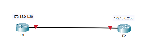
- R1: 172.18.0.1/30
- R2: 172.18.0.2/30
Though in the real world you sometimes see /31, stick with /30 for the CCNA.
Shutting Down vs. Enabling
- To disable an interface: You must be in interface config mode:
Router(config-if)# shutdown - To re-enable it:
Router(config-if)# no shutdown
Administratively down just means the interface is disabled by a shutdown command. The hardware might be fine, but the software is keeping it off until you use no shutdown. If you see "administratively down," it means you or someone else shut it down.
Verification Commands:
Always check your config after you’re done. These are essential CCNA commands:
- Quick Status Check:
Router# show ip interface brief
You want to see the correct IP and Status up, Protocol up.- up/up = Great!
- up/down = Physical link is up, but a Layer 2 protocol issue (like encapsulation mismatch).
- administratively down/down = You forgot no shutdown or intentionally shut it down.
- Detailed Status:
Router# show interfaces serial 0/0/0 - Detailed IP Check:
Router# show ip interface serial 0/0/0
Common Mistakes (And How to Fix Them)
- Wrong Mask: If neighbors can’t ping, check that both IPs are in the same subnet!
- Still Shut Down: If show ip int brief says “administratively down,” go back and type Router(config-if)# no shutdown.
- Missing IP: If the interface is up but has no IP, go back and add it: ip address <ip> <mask>.
- Duplicate IP: If you get logs about a duplicate address, change one of the IPs to make it unique within the subnet.
Example Configs
A. Serial Link (/30)
Router 1:
Router1# conf t
Router1(config)# interface S0/0/0
Router1(config-if)# ip address 172.18.0.1 255.255.255.252
Router1(config-if)# no shutdown
Router 2: (Same process, different IP)
Router2# conf t
Router2(config)# interface S0/0/0
Router2(config-if)# ip address 172.18.0.2 255.255.255.252
Router2(config-if)# no shutdown
B. LAN Interface (GigabitEthernet)
Router1# conf t
Router1(config)# interface G0/0
Router1(config-if)# ip address 192.168.10.1 255.255.255.0
Router1(config-if)# no shutdown
Exam Takeaways
Memorize These Commands:
- configure terminal
- interface <type> <number>
- ip address <ip> <mask>
- shutdown
- no shutdown
- show ip interface brief
Key Concepts to Remember:
- You must have an IP on any Layer 3 interface.
- shutdown makes the interface administratively down.
- Use /30 for most point-to-point links.
- Always verify with show ip interface brief.
Exercise caution regarding potential exam-specific deceptive scenarios. For instance, a presented interface might display an operational status (up/up) but lack an assigned IP address, thereby preventing IPv4 routing. Furthermore, you may be tested on command mode specificity; for example, the shutdown command is exclusively executable within interface configuration mode.
Summary
- Assigning an IPv4 address + subnet mask to a Cisco router interface makes it a Layer 3 interface associated with a specific subnet, enabling IPv4 send/receive and routing/forwarding via the routing table.
- For Layer 3 operation, an interface must have:
- IPv4 address
- Subnet mask (prefix)
- Be enabled (
no shutdown)
- If an interface has no IP, the router cannot use it for IPv4 forwarding.
- IOS modes used for interface setup:
Router#(Privileged EXEC)Router(config)#(Global Config)Router(config-if)#(Interface Config)
- Core interface commands:
ip address <ip> <mask>no shutdown/shutdown
- Standard configuration sequence:
configure terminalinterface <type/number>ip address <ip> <mask>no shutdown
- CCNA subnetting note: use /30 for classic point-to-point links.
- Verify and troubleshoot with:
show ip interface briefshow interfaces <int>show ip interface <int>
- Common issues: wrong mask, interface shutdown, missing IP, duplicate IP.
- Exam traps: interface can be up/up but unusable for IPv4 if it has no IP;
shutdownis only in interface config mode.
You configured the interface (IP/mask, speed/duplex, description), but it won’t pass traffic unless:
- Admin state is up: interface not shut (no shutdown).
- Layer 1 is up: link/cable/optic/remote port is physically up.
- Layer 2 is up: correct L2 mode/encapsulation (VLAN/trunk/PPP/HDLC, etc.).
- Layer 3 is correct: right IP + prefix, no duplicates, correct subnet.
- Routing exists: connected/local routes appear; beyond-subnet traffic needs routes/default route.
- No blocks: ACLs, port-security/errdisable, policies, VRF mismatch.
Verification:
show ip interface brief
show interfaces g0/0
show ip route- It has to be turned on (not shutdown).
- The physical stuff has to be good (cable, optics, the device on the other end).
- The Layer 2 part has to be happy (VLANs, trunking, encapsulation).
- It needs the right Layer 3 setup (correct IP, subnet, and routing expectations).
For the CCNA, interface checking is one of the most common things you’ll troubleshoot. You’ll be using a handful of show commands over and over to confirm:
- Is the link up?
- Does it have the correct IP?
- Is Layer 1/Layer 2 healthy?
- Are there error messages piling up?
- Did it learn the right routes?
The main commands you’ll use are:
- show ip interface brief
- show protocols
- show interfaces —— (you can check just one interface)
First Look: show ip interface brief
This is your go-to command. It gives you a quick table showing:
- Interface name
- IP address
- If the IP is valid (OK?)
- How the IP was set (Method)
- Layer 1 status (Status)
- Layer 2 status (Protocol)
You usually run this first because it instantly tells you which interfaces need a deeper look.
How to Read It Fast
- up / up ——- You’re good to go!
- administratively down / down ——- Someone (maybe you) shut it down in the config.
- down / down ——- Physical problem (bad cable, nothing plugged in, or the other side is off).
- up / down ——– Link is physically fine, but Layer 2 is messed up (often a config mismatch).
Second Look: show protocols
- This is great when you just want a small snapshot.
- Example: show protocols ethernet 0/0
It provides the two-part status line (hardware + line protocol) and the configured IP/prefix length. Handy for a quick check of the essentials (status + IP).
Deep Dive: show interfaces
This output is long, but it’s the place to find out why something is failing:
- Speed/duplex results
- Encapsulation type
- Error counters (CRC, drops, etc.)
- Traffic rates
Key Stuff You Need to Know
- GigabitEthernet0/0 is up, line protocol is up
- First part: The physical connection (Layer 1).
- Second part: The data link connection (Layer 2).
- Description: Super helpful for knowing what the link goes to.
- Internet address: The IP and prefix.
- MTU: The maximum packet size (usually 1500 on Ethernet).
- BW / DLY: Used by routing protocols to figure out the best path.
- Reliability / Load: Shows connection quality and current traffic load.
- Error counters: Watch these! They tell you if you have a physical issue (like a bad cable causing CRCs).
Pro Tip: Shorten Your Commands: IOS lets you use abbreviations. sh int fa0/0 is much faster than show interfaces FastEthernet0/0 —— a real time-saver.The 4 Status Combinations
Every interface reports two statuses:
Layer 1 (Hardware) and Layer 2 (Line Protocol).
A) administratively down, down
- The configuration indicates a shutdown state.
- Quick Fix: Go into config mode and type no shutdown.
B) down, down
- The functionality is enabled, yet a physical link failure is occurring.
- Primary Cause: Bad cable, the device on the other side is off, or the remote port is shut down.
- What to Do: Check link lights, swap the cable, and check the remote end’s config.
C) up, down
- The physical link integrity is confirmed, but the Layer 2 functionality is impaired.
- Primary Cause: An encapsulation mismatch (like PPP vs. HDLC on serial links) or a VLAN/trunking problem.
- What to Do: Check the encapsulation settings on both ends.
D) up, up
- The interface is functioning correctly.
- Next Step: If you still have a problem, it’s probably a Layer 3 issue (wrong IP, wrong mask, or a routing problem).
- Routing Check: Connected and Local Routes
This is important
When you put an IP address on an interface, the router automatically does two things in the routing table:
- It installs the subnet as a connected route (marked with C).
- It installs the interface’s exact IP as a local route (marked with L, with a /32 mask).
Command: show ip route
If your interface is up/up and you don’t see these routes, something is seriously wrong with the IP config.
A Practical Troubleshooting Flow
- Big Picture: show ip interface brief (Find anything not up/up).
- Focus: show protocols gigabitEthernet 0/0 (Confirm status and IP).
- Details: show interfaces gigabitEthernet 0/0 (Check duplex, errors, and encapsulation).
- Routing: show ip route (Verify the C and L routes are there).
- (If needed) Test: ping <neighbor-ip> or traceroute <destination-ip>
Interface Config Basics
—— Set it up!
conf t
interface g0/0
description Link to ISP
ip address 192.168.2.1 255.255.255.0
no shutdown
end
—— Turn it off/on
conf t
interface g0/0
shutdown  <- Turns it off
no shutdown  <- Turns it on
end
Quick CCNA Tips
- Start with show ip interface brief—it’s the fastest way to spot issues.
- If you see administratively down, run no shutdown. Don’t check the cable!
- down/down means physical problem (cable, power, remote shutdown).
- up/down means Layer 2 mismatch (encapsulation).
- Always check for the C and L routes in the routing table after configuring an IP.
- Use abbreviations (show int br) to save time.
Summary
- Admin up: interface not shutdown (no shutdown)
- Layer 1 up: physical link OK (cable/optic/remote port)
- Layer 2 up: correct VLAN/trunk/encapsulation (up/down = L2 issue)
- Layer 3 correct: right IP/prefix/subnet, no duplicates
- Routing present: C (connected) and L (local) routes exist; other networks need routes/default route
- No blocking features: ACLs, port-security/errdisable, policies, VRF mismatch
Lab ID: LABS-PT-20260114-A7KQ
Introduction
This lab is not pre-built. Build this entire lab in Packet Tracer. No templates ——you are responsible for the full topology and configuration. Prove it works by testing connectivity and validating every requirement. If you haven’t installed it yet or don’t know how to use the simulator, go to: https://fromzerotoccna.com/packet-tracer/
Objective: Create a scenario that covers all the requested topics.
Configure IPv4 addresses on Cisco router 2911 interfaces so that PC1 (LAN1) can communicate with PC2 (LAN2) through a routed WAN link. Then verify interface status and end-to-end connectivity using show commands and ping from both routers and PCs.
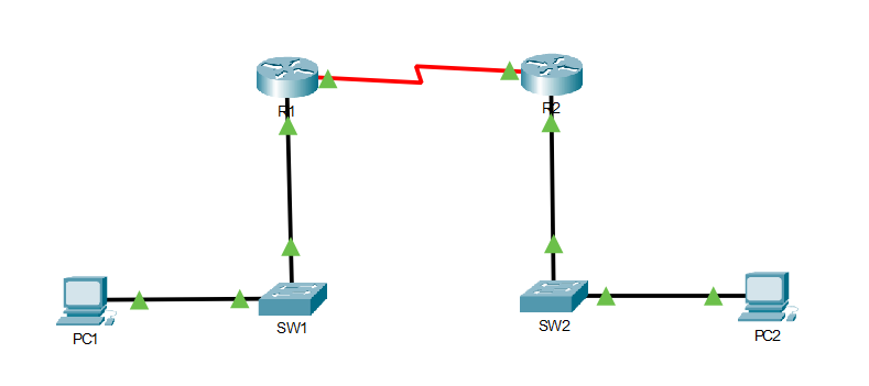
TOPOLOGY
Devices (rename them):
- Router1 → R1
- Router2 → R2
- Switch1 → SW1
- Switch2 → SW2
- PC0 → PC1
- PC1 → PC2
Physical connections (ports must match exactly):
- R1 G0/0 ↔ SW1 F0/1
- SW1 F0/2 ↔ PC1 NIC
- R2 G0/0 ↔ SW2 F0/1
- SW2 F0/2 ↔ PC2 NIC
- R1 S0/0/0 ↔ R2 S0/0/0 (Serial link; one side must be DCE)
Note: If you use the 2911 router (for example), you must install this module: HWIC-2T — a Cisco 2-Port Serial High-Speed WAN Interface Card that provides two serial ports.Cabling rules (Assume Auto-MDI/MDIX is disabled):
- Router ↔ Switch: Copper Straight-Through
- Switch ↔ PC: Copper Straight-Through
- Router ↔ Router (Serial): Serial DCE on one end and Serial DTE on the other
- For configuration access: Console cable from a PC to each router (optional but recommended)
Command Summary (Packet Tracer CLI)
| Command | Description |
|---|---|
| enable | Enter privileged EXEC mode |
| configure terminal | Enter global configuration mode |
| hostname R1 / hostname R2 | Rename the router |
| interface g0/0 | Enter interface configuration mode (Gigabit) |
| interface s0/0/0 | Enter interface configuration mode (Serial) |
| description <text> | Add an interface description |
| ip address <ip> <mask> | Assign an IPv4 address to an interface |
| no shutdown | Enable the interface |
| clock rate 64000 | Set DCE clocking on the serial DCE interface |
| end | Exit configuration mode |
| copy running-config startup-config | Save configuration |
| show ip interface brief | Verify interface IPs and up/down status |
| show interfaces s0/0/0 | Verify serial details (DCE/DTE, line protocol) |
| show running-config | Confirm configured IPs and interface settings |
| ping <ip> | Test reachability |
| traceroute <ip> | Verify path (optional) |
| ip route <network> <mask> <next-hop> | Configure static routes for end-to-end connectivity |
| show ip route | Verify routing table |
IP Address Table
| Device | Interface | IP Address | Subnet Mask | Default Gateway | VLAN | Notes |
| R1 | G0/0 | 192.168.10.1 | 255.255.255.0 | N/A | N/A | LAN1 gateway |
| R1 | S0/0/0 | 10.0.0.1 | 255.255.255.252 | N/A | N/A | WAN link (set clock rate if DCE) |
| R2 | G0/0 | 192.168.20.1 | 255.255.255.0 | N/A | N/A | LAN2 gateway |
| R2 | S0/0/0 | 10.0.0.2 | 255.255.255.252 | N/A | N/A | WAN link |
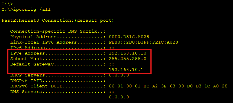
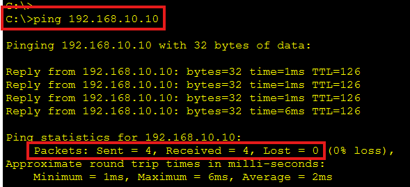
| PC1 | NIC | 192.168.10.10 | 255.255.255.0 | 192.168.10.1 | N/A | Host in LAN1 |
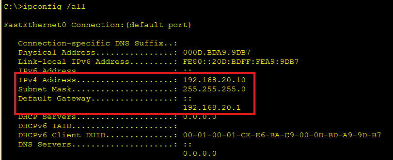
| PC2 | NIC | 192.168.20.10 | 255.255.255.0 | 192.168.20.1 | N/A | Host in LAN2 |
Lab Tasks
Task 1: Build the topology and prepare devices
What you will do: Place devices, connect them with correct cables, and rename them.
- Add 2 routers, 2 switches, and 2 PCs to the workspace.
- Cable the devices exactly as shown in the topology section (use correct cable types).
- Rename devices to: R1, R2, SW1, SW2, PC1, PC2.
Task 2: Configure IPv4 addresses on router interfaces (and bring them up)
What you will do: Assign IPv4 addresses to router interfaces and ensure interfaces are operational.
- Configure R1 G0/0 and R1 S0/0/0 with the IPs in the IP table.
- Configure R2 G0/0 and R2 S0/0/0 with the IPs in the IP table.
- Ensure all interfaces are enabled (no shutdown) and serial clocking is set on (64000) the DCE side.
- Verify interface status using show ip interface brief.
Task 3: Verify connectivity (local, WAN, and end-to-end)
What you will do: Confirm that addressing is correct and traffic can pass from PC1 to PC2.
- Configure PC1 and PC2 with the IPs/default gateways in the IP table.
- Ping each router’s LAN interface from its local PC.
- Ping across the WAN between routers (serial interface to serial interface).
- Add static routes so LAN1 and LAN2 can reach each other, then ping PC1 ↔ PC2.

Lab Solution
Task 1 Solution: Build the topology and prepare devices
- Place devices: Add two routers (example: 2811/2911), two 2960 switches, and two PCs.
- Add serial interfaces if needed: If your router model doesn’t have serial ports by default, power off the router and add a serial module (e.g., HWIC-2T/WIC-2T), then power it back on.
- Cable correctly (Assume Auto-MDI/MDIX is disabled) Use Straight-through for: R1 G0/0 ↔ SW1 F0/1 | SW1 F0/2 ↔ PC1 NIC | R2 G0/0 ↔ SW2 F0/1 | SW2 F0/2 ↔ PC2 NIC. Use Serial cable for: R1 S0/0/0 ↔ R2 S0/0/0 (use Serial DCE on one side)
- Rename routers (do both routers)
- On Router1:
- Router> enable
- Router# configure terminal
- Router(config)# hostname R1
- R1(config)# end
- On Router2:
- Router> enable
- Router# configure terminal
- Router(config)# hostname R2
- R2(config)# end
Task 2 Solution: Configure IPv4 addresses on router interfaces (and bring them up)
On R1
Configure G0/0
R1> enable
R1# configure terminal
R1(config)# interface g0/0
R1(config-if)# description LAN1 to SW1
R1(config-if)# ip address 192.168.10.1 255.255.255.0
R1(config-if)# no shutdown
R1(config-if)# exit
Configure S0/0/0
R1(config)# interface s0/0/0
R1(config-if)# description WAN to R2
R1(config-if)# ip address 10.0.0.1 255.255.255.252
R1(config-if)# no shutdown
If R1 is the DCE side, set clock rate (only on the DCE end)
R1(config-if)# clock rate 64000
R1(config-if)# exit
R1(config)# end
Verify interfaces
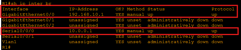
R1# show ip interface brief
R1# show interfaces s0/0/0
Success looks like: the interfaces show up/up (not administratively down).
On R2
Configure G0/0
R2> enable
R2# configure terminal
R2(config)# interface g0/0
R2(config-if)# description LAN2 to SW2
R2(config-if)# ip address 192.168.20.1 255.255.255.0
R2(config-if)# no shutdown
R2(config-if)# exit
Configure S0/0/0
R2(config)# interface s0/0/0
R2(config-if)# description WAN to R1
R2(config-if)# ip address 10.0.0.2 255.255.255.252
R2(config-if)# no shutdown
R2(config-if)# exit
R2(config)# end
Verify interfaces
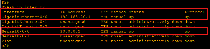
R2# show ip interface brief
R2# show interfaces s0/0/0
Save configs (do on both routers)
R1# copy running-config startup-config
R2# copy running-config startup-config
Task 3 Solution: Verify connectivity (local, WAN, and end-to-end)
Configure PC IP settings (Packet Tracer)
- PC1: Desktop → IP Configuration
- IP: 192.168.10.10
- Mask: 255.255.255.0
- Gateway: 192.168.10.1
- PC2: Desktop → IP Configuration
- IP: 192.168.20.10
- Mask: 255.255.255.0
- Gateway: 192.168.20.1
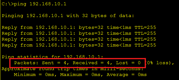
Local pings (each PC to its router LAN interface)
From PC1 Command Prompt:
ping 192.168.10.1
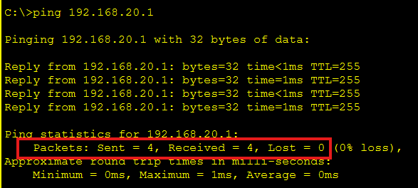
From PC2 Command Prompt:
ping 192.168.20.1
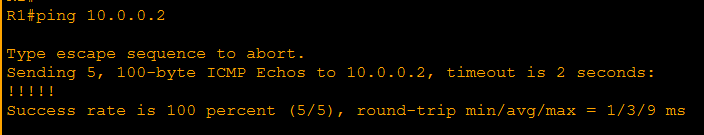
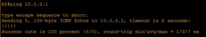
WAN ping (router to router serial)
From R1:
R1# ping 10.0.0.2
From R2:
R2# ping 10.0.0.1
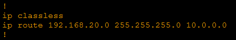
Enable end-to-end LAN reachability (static routes) Because each router only knows its directly connected networks, add routes:
On R1 (route to LAN2 via R2 serial IP):
R1# configure terminal
R1(config)# ip route 192.168.20.0 255.255.255.0 10.0.0.0
R1(config)# end
R1# show ip route
On R2 (route to LAN1 via R1 serial IP):
R2# configure terminal
R2(config)# ip route 192.168.10.0 255.255.255.0 10.0.0.0
R2(config)# end
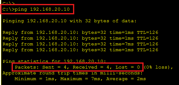
R2# show ip routeFinal verification (PC to PC)
From PC1:
ping 192.168.20.10
From PC2:
ping 192.168.10.10
If something fails, check these fast:
- show ip interface brief (look for up/up)
- Ensure you used no shutdown
- Ensure serial clock rate is set on the DCE side
- PC default gateways match the router LAN interface IPs
- show ip route includes both static routes
[Return to CCNA Study Hub] — Next Stop: [Section 2 | Connected Device Discovery]