
Across a Router and Switching Behavior
What this section covers
This section explains what happens behind the scenes when one IPv4 host sends traffic to
another IPv4 host on a different subnet. The focus is on the exact forwarding behavior at
Layer 2 (Ethernet) and Layer 3 (IPv4), including ARP resolution, routing-table lookup, and
MAC-table learning in a switch.
Scenario used throughout
- Host A: 192.168.3.1/24, default gateway 192.168.3.2
- Router R1: G0/0 192.168.3.2/24, G0/1 192.168.4.1/24
- Host B: 192.168.4.2/24, default gateway 192.168.4.1
Core rules
- IP addresses identify the end hosts (end-to-end).
- MAC addresses identify the next hop on the local segment (hop-by-hop).
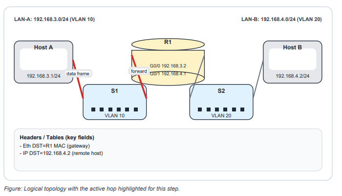
- For a remote destination: IP DST = remote host, Ethernet DST MAC = default gateway MAC.
- ARP resolves IPv4 to MAC only within the local broadcast domain (VLAN).
- Routers rewrite Layer 2 headers per hop; switches forward frames without modifying them.
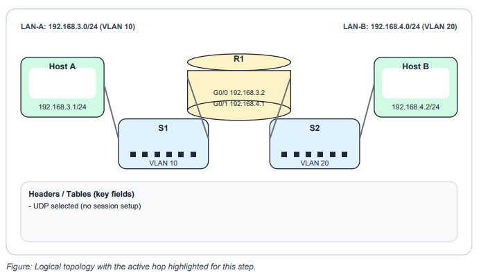
Step 1 | Application data and UDP selection
Host A (192.168.3.1) has application data to send to Host B (192.168.4.2). The application does not require a reliable connection, so it selects UDP and begins sending data.
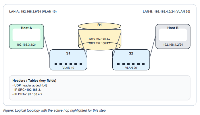
Step 2 | UDP Encapsulation & IPv4 Packet
UDP adds a UDP header (ports). IPv4 encapsulates the segment into an IP packet and sets the source IP to 192.168.3.1 and the destination IP to 192.168.4.2
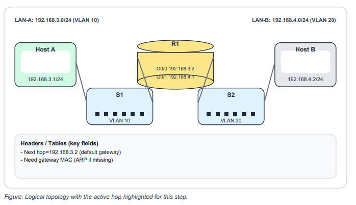
Step 3 | Subnet check and next-hop decision
Host A determines the destination IP is on a different IPv4 network. The packet must be sent to the default gateway (192.168.3.2). Host A cannot transmit the Ethernet frame until it knows the gateway MAC address.
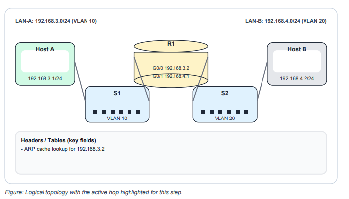
Step 4 I ARP lookup for the default gateway
Host A checks its ARP cache for an entry for 192.168.3.2. If no entry exists, the packet is held while ARP resolves the gateway MAC address.
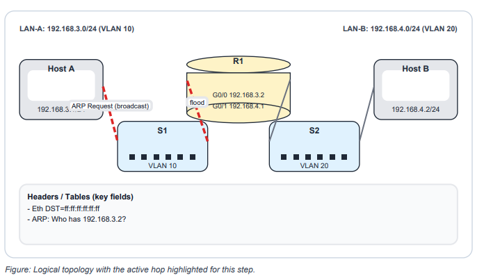
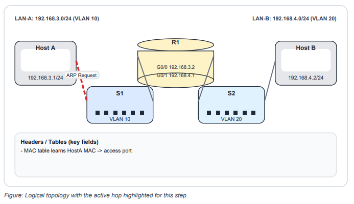
Step 5 | ARP Request broadcast for gateway MAC
Host A sends an ARP Request as an Ethernet broadcast ff:ff:ff:ff:ff:ff asking for the MAC address of 192.168.3.2
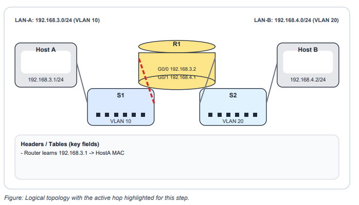
Step 6 | Router Learns Host A (ARP Request)
The router receives the ARP Request. Like any IPv4 node, it can learn the sender mapping and add Host A’s IP-to-MAC entry into its ARP table.
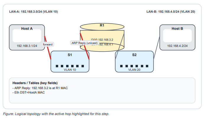
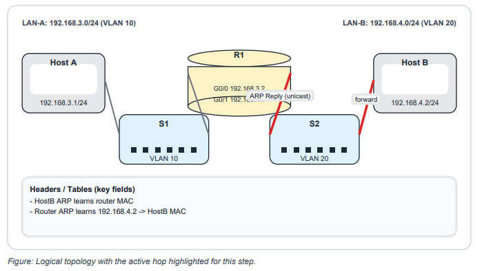
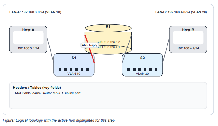
Step 7 | ARP Reply unicast from router to Host A
The router replies with an ARP Reply sent as a unicast frame back to Host A, providing the
router MAC address for 192.168.3.2
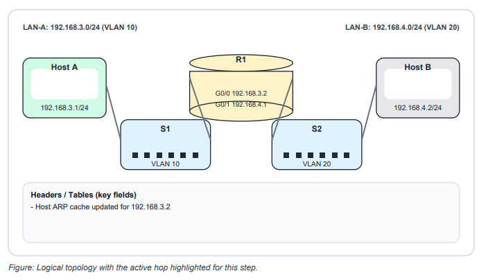
Step 8 | Host A updates ARP cache
Host A receives the ARP Reply and stores the mapping 192.168.3.2 -> (router MAC) in its ARP cache.
Step 9 | Data frame sent to the default gateway
Host A transmits the data in an Ethernet frame addressed to the default gateway MAC. The
destination IP remains the remote host (192.168.4.2).
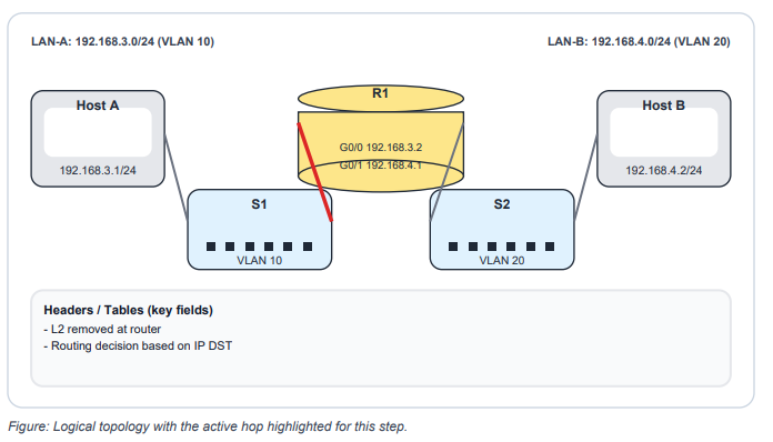
Step 10 | Router receives frame and invokes routing
The router receives the frame (destination MAC matches). It decapsulates Layer 2, checks the destination IP, and forwards the packet through the routing process (instead of consuming it).
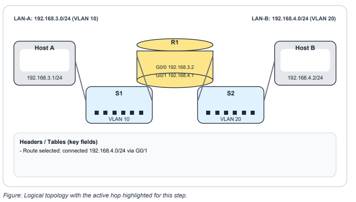
Step 11 | Routing table lookup (longest prefix match)
The router performs a longest prefix match for 192.168.4.2. The destination network 192.168.4.0/24 is directly connected, so the router selects its 192.168.4.1 interface for forwarding.
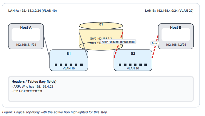
Step 12 | Router ARP on destination LAN for Host B
To forward on the 192.168.4.0/24 segment, the router needs Host B’s MAC. If the mapping is missing, the router broadcasts an ARP Request for 192.168.4.2 on the destination LAN.
Step 13 | Host B replies; ARP tables update
Host B processes the ARP Request, stores the router mapping, and sends an ARP Reply back to the router. The router stores Host B’s IP-to-MAC entry.
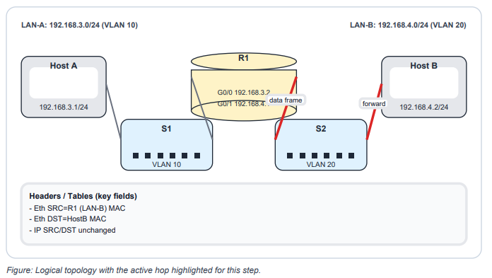
Step 14 | Router forwards frame to Host B
The router forwards the packet to Host B by encapsulating it in a new Ethernet frame on LAN-B. Layer 2 addresses change per hop; Layer 3 addresses remain end-to-end.
Switch Step
Step 1 | Switch learns Host A MAC via ARP
Before the ARP Request reaches other devices, the switch receives the broadcast frame. The switch learns the source MAC and records it in the MAC address table for the VLAN.
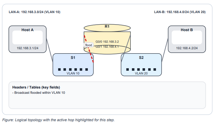
Step 2 | Switch floods the broadcast in the VLAN
Because the destination MAC is broadcast, the switch floods the frame out all other ports in the VLAN except the ingress port.
Step 3 | ARP Reply Updates Switch MAC Table
The router sends an ARP Reply as a unicast frame. The switch learns the router MAC on the router-facing port and adds it to the MAC address table.
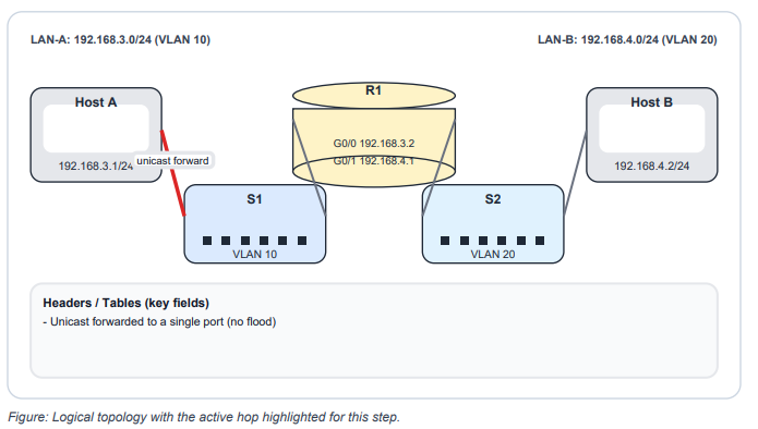
Step 4 | MAC Table Unicast Forwarding (Host A)
The ARP Reply destination MAC is Host A. The switch looks up Host A’s MAC in the table and forwards the unicast frame only out the correct port.
Configuration Reference
Router (R1) | two directly connected LANs
conf t
hostname R1
interface g0/0
description LAN-A 192.168.3.0/24
ip address 192.168.3.2 255.255.255.0
no shutdown
interface g0/1
description LAN-B 192.168.4.0/24
ip address 192.168.4.1 255.255.255.0
no shutdown
end
write memory
Switch (S1) | access VLAN for Host A and router uplink
conf t
hostname S1
vlan 10
name USERS
interface fa0/1
description Host-A
switchport mode access
switchport access vlan 10
spanning-tree portfast
spanning-tree bpduguard enable
interface fa0/3
description Uplink-to-R1-g0/0
switchport mode access
switchport access vlan 10
end
write memory
Best Practices and Troubleshooting
Best practices (CCNA baseline)
- Document default gateways and keep VLAN-to-subnet mapping consistent (one VLAN to one subnet in simple designs).
- On host-facing switch ports, enable spanning-tree portfast and bpduguard to reduce loop risk and speed access.
- Use interface descriptions and save configuration after changes (write memory).
- Validate VLAN membership and link state before debugging routing or ACLs.
Troubleshooting workflow (repeatable)
- Layer 1 and 2: show interfaces status, show vlan brief, show mac address-table (switch); show
ip interface brief (router). - Host config: confirm IP address, mask, and default gateway.
- ARP: show ip arp on the router. Missing entries usually indicate VLAN mismatch, IP/mask
mismatch, or L2 reachability issues. - Routing: show ip route. Connected routes should appear when interfaces are up with correct
IP addressing. - Progressive tests: ping default gateway; ping both hosts from the router; ping remote host
end-to-end; traceroute for hop visibility.
Hands-on labs
- Lab 1 (Baseline): Configure R1 and hosts. Verify Host A can ping 192.168.3.2, Host B can ping 192.168.4.1, and Host A can ping Host B.
- Lab 2 (Observe ARP/MAC): Clear ARP (clear ip arp) and clear dynamic MAC entries (clear mac address-table dynamic if supported).
- Generate traffic and observe ARP and MAC tables repopulate.
- Lab 3 (Break/Fix): Introduce one fault at a time (wrong default gateway, wrong VLAN, shutdown interface, duplicate IP). Document symptoms and the command outputs that prove root cause
Review questions
- When Host A sends to a remote subnet, what MAC address is used as the Ethernet destination?
- What destination MAC is used for an ARP Request?
- What does a switch learn when it builds the MAC address table?
- What changes when a router forwards a packet to the next segment?
- Why cannot two hosts in different subnets communicate using only a Layer 2 switch?
- Default gateway MAC (router interface MAC on Host A subnet).
- ff:ff:ff:ff:ff:ff (broadcast).
- Source MAC and ingress port (per VLAN).
- Layer 2 headers change (new SRC/DST MAC); TTL decrements; IP SRC/DST stays end-to-end.
- A Layer 2 switch forwards within a VLAN/broadcast domain; inter-subnet traffic requires Layer 3 routing.
[Return to CCNA Study Hub] — Next Stop: [Section 3 | Troubleshooting Methods] …Available Soon!