
Internet Protocol (IP): Moving packets with logic, not promises.
IP: Layer 3, connectionless, best-effort addressing and routing.
First Listen: let your ears lead the way before your mind takes notes.
📻 FZ2CCNA Radio:
Then read: let your eyes explore before your mind starts to explain.
Where Does IP Operate?
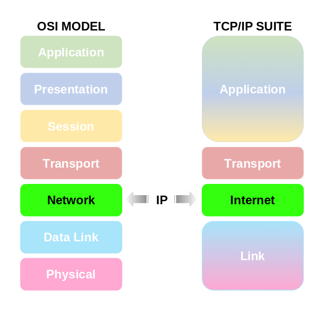
In the OSI Model:
Internet Protocol (IP) works at Layer 3 – the Network Layer.
- This layer is responsible for logical addressing (IP addresses),
- path determination (choosing routes), and
- packet forwarding (delivering data from one device to another across multiple networks).
In the TCP/IP Model: IP lives in the Internet Layer. Here, it does the same job: moving packets across networks, deciding how they get from source to destination.Other protocols like TCP and UDP sit above it in the Transport Layer, while Ethernet and Wi-Fi sit below it in the Network Access Layer.
Why It Matters for CCNA
- When you think IP = Layer 3, always remember: addressing + routing.
- The main tools of this layer are IP addresses, subnets, and routing tables.
- In the OSI world, you’ll hear “Network Layer.”
- In the TCP/IP world, you’ll hear “Internet Layer.”
Same job, different name…
15 Key Characteristics of IP (Internet Protocol)
Connectionless protocol
IP does not set up a dedicated connection between sender and receiver. Each packet is sent independently. In practical terms, this means that IP is a connectionless protocol. Unlike a telephone call, where a line is reserved for both parties before any conversation starts, IP does not reserve resources or build a session before sending data.
When an application generates data, IP immediately breaks it into packets (datagrams) and sends them out onto the network. Each packet contains the source IP address (where it came from) and the destination IP address (where it should go). After that, every packet is treated as a separate unit of delivery.
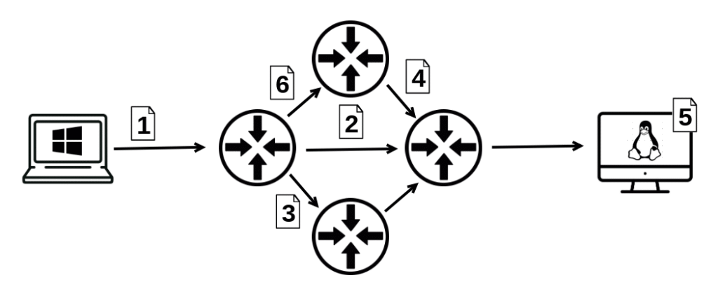
Because packets are independent:
- They may take different routes through the network.
- They may arrive out of order.
- Some may be lost or duplicated along the way.
It’s important to understand that IP itself does not fix these issues. Its job ends at delivery attempts. Higher-level protocols like TCP add reliability, sequencing, and retransmission if necessary.
This design is what makes IP scalable and flexible. Networks don’t waste time and resources setting up or maintaining connections for every communication. Instead, they just forward packets as they come, making it possible for billions of devices to share the Internet efficiently.
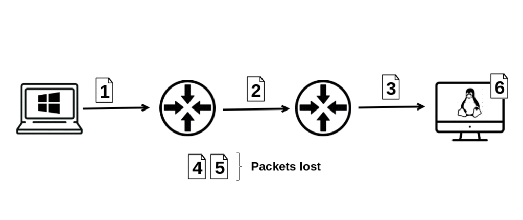
Best-effort delivery
IP does not guarantee delivery, order, or error checking. If packets are lost or duplicated, higher-layer protocols (like TCP) must handle it. Internet Protocol (IP) is often described as a connectionless, best-effort protocol. This means that when IP sends a packet across the network, it does not make any promises about what will happen to that packet.
- No Delivery Guarantee:
IP does not confirm that a packet has reached its destination. If a router drops the packet because of congestion or errors, IP does not retransmit it. From IP’s perspective, once the packet is sent, its job is done. - No Order Guarantee:
IP does not ensure that packets arrive in the same order they were sent. Because different packets may take different paths through the network, one packet can arrive later than another, even if it was sent earlier. - No Error Checking of Data:
IP only checks the integrity of its header (using a checksum in IPv4). It does not verify that the actual data (payload) inside the packet is error-free. If corruption happens in the payload, IP itself does nothing about it.
Because of these limitations, IP relies on higher-layer protocols to add reliability:
- UDP (User Datagram Protocol), by contrast, adds no reliability, but is often used where speed is more important than accuracy (like streaming or gaming).
- TCP (Transmission Control Protocol) handles missing, out-of-order, or duplicated packets. It provides acknowledgments, retransmissions, and reordering, ensuring that data arrives intact and in sequence.
Packet switching
Data is divided into packets (datagrams). Each packet is routed separately across the network. When data is transmitted over an IP-based network, it is not sent as one continuous stream. Instead, IP divides the data into smaller, manageable units called packets (or datagrams).
- Why This Matters: This packet-based system makes IP networks scalable and resilient. Even if one path is congested or fails, packets can be rerouted through alternate paths, ensuring the network continues to function.
- Structure of a Packet: Each packet contains two parts:
- Header – information about where the packet is from, where it’s going, and how to handle it (e.g., source and destination IP addresses, TTL, protocol type).
- Payload – the actual piece of data being delivered.
- Independent Routing: Each packet is treated independently. Routers examine the destination IP address in the header and decide the next best hop toward that destination. This means:
- Packets belonging to the same message or file may take different paths through the network.
- Some packets may arrive earlier, some later, and some may not arrive at all.
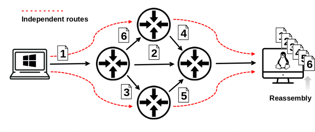
Reassembly at the Destination: The receiving host uses sequence numbers (from higher-layer protocols like TCP) to reassemble packets in the correct order, recreating the original message.
Logical addressing
Every device gets an IP address (IPv4 or IPv6). This address identifies the device in the network logically, not physically. Every device connected to a network must have a way to be identified so data knows where to go. IP provides this identification through an IP address.
This does not change unless you replace or reprogram the NIC.
IP Address (Logical Address):
- An IP address is not tied to the hardware itself, but rather assigned to the device’s network interface.
- It can be configured manually (static) or given automatically by DHCP (dynamic).
- Because it’s logical, it can be changed or reassigned without replacing the physical hardware.
- Example: Your laptop might have
192.168.1.25today at home and a completely different IP when you connect to Wi-Fi at a coffee shop.
- Example: Your laptop might have
IPv4 vs IPv6:
- IPv4 uses 32 bits (e.g.,
192.168.1.1), allowing about 4.3 billion unique addresses. - IPv6 uses 128 bits (e.g.,
2001:db8::1), providing an almost unlimited number of addresses.
Physical Address (MAC Address):
- In contrast, the physical address (MAC address) is burned into the network card by the manufacturer.
- Example:
00:1A:2B:3C:4D:5E. - This does not change unless you replace or reprogram the NIC.
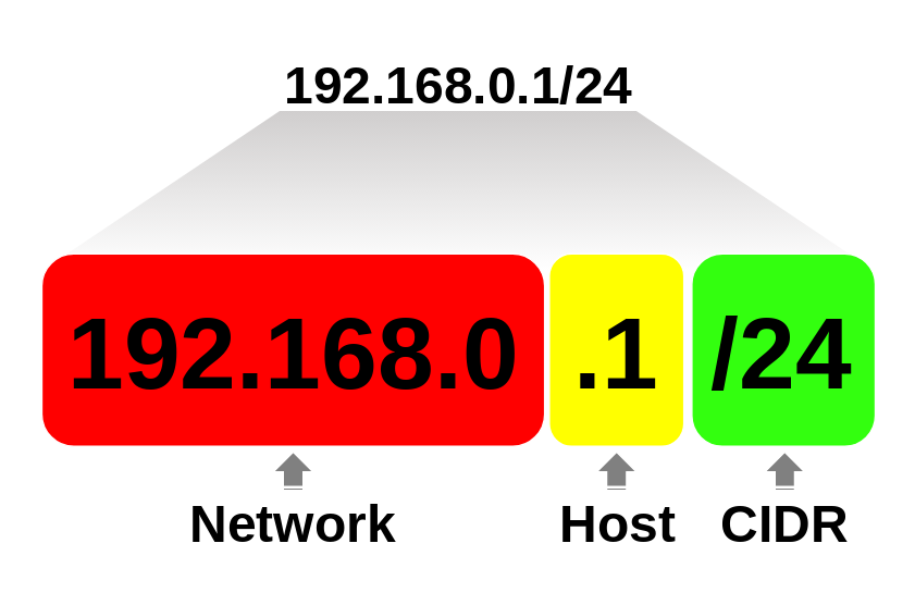
Hierarchical addressing
An IP address has two parts:
- Network portion → identifies the network.
- Host portion → identifies the device inside that network.
- CIDR, or Classless Inter-Domain Routing, is a method for allocating and routing IP addresses that allows a single IP address to represent a range of addresses
An IP address is not just a random number. It’s carefully designed to tell two stories at once:
- Which network the device belongs to
- Which specific device it is inside that network
This is possible because every IP address has two logical parts:
Network Portion
- The network portion identifies the overall network segment.
- All devices within the same network share the same network portion of their IP address.
- Think of it like a street name: if everyone lives on “Maple Street,” then “Maple Street” is the network portion.
- Example: In the address
192.168.0.1with a subnet mask of255.255.255.0:- The network portion is
192.168.1. - That means this device belongs to the
192.168.1.0network.
- The network portion is
Host Portion
- The host portion identifies the specific device within that network.
- Each device (PC, phone, printer, router interface) gets a unique host number in that network.
- Think of it like a house number: “Maple Street” tells you the neighborhood, but “123” tells you which exact house.
- Continuing the example
192.168.0.1:- The host portion is 1
- That’s the unique device ID inside the
192.168.1.0network.
The Role of the Subnet Mask
The subnet mask (or prefix length in CIDR notation, e.g., /24) tells us where the network portion ends and the host portion begins.
- In
255.255.255.0(or/24), the first 24 bits (192.168.0) are the network, and the last 8 bits (.1) are the host. - This boundary is what allows routers to know how to forward packets.
Why This Matters in Networking
- Routers only care about the network portion to forward packets toward the right destination.
- Once the packet reaches the correct network, the host portion ensures it lands on the right device.
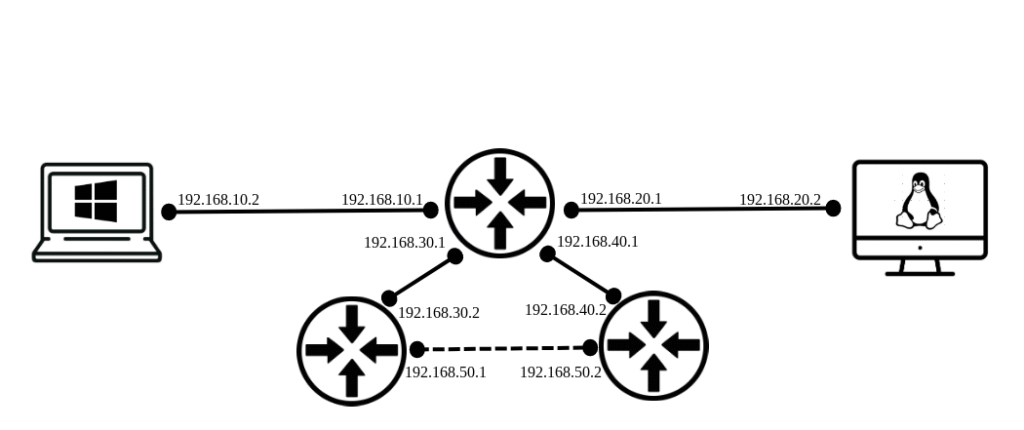
Routing capability
Routers use IP addresses to forward packets between different networks until they reach the destination. Routers are the devices that make the Internet work, and their primary job is to move packets from one network to another. Unlike switches, which forward frames within the same local network, routers operate at Layer 3 (the Network Layer) and make decisions based on IP addresses.
When a router receives a packet:
- It looks at the destination IP address inside the packet’s header.
- Example: (IPv4)
192.168.10.25or (IPv6)2001:db8::5.
- Example: (IPv4)
- It checks its routing table — a list of known networks and the best next hop (interface or neighbor router) for each one.
- It decides where to send the packet next.
- If the destination network is directly connected, the router sends the packet straight to that network.
- If not, it forwards the packet to another router, closer to the destination.
- This process repeats hop by hop across multiple routers until the packet eventually arrives at the destination network and then to the specific host.
Routers don’t care about the contents of the packet (the actual email, video, or file). They only care about the IP address — the logical location of where the packet needs to go.
Encapsulation
IP wraps data in an IP packet, which is then placed inside a data link frame (Ethernet, Wi-Fi, etc.). When data is sent across a network, it doesn’t travel as raw information. Instead, it is encapsulated layer by layer following the OSI or TCP/IP model.
- At the Transport Layer (Layer 4)
- Protocols like TCP or UDP take the application data (for example, a web request) and break it into segments.
- Each segment includes source and destination port numbers so the receiving device knows which application the data belongs to.
- At the Network Layer (Layer 3)
- The segment is passed down to the Internet Protocol (IP).
- IP adds its own header, which includes:
- Source IP address
- Destination IP address
- TTL (Time To Live)
- Protocol field (to indicate TCP, UDP, ICMP, etc.)
- Now the data becomes an IP packet.
- At the Data Link Layer (Layer 2)
- The IP packet is wrapped inside a frame specific to the network technology being used.
- If it’s Ethernet, the frame includes:
- Source MAC address
- Destination MAC address
- Error-checking information (FCS).
- If it’s Wi-Fi, the frame uses a different format but serves the same purpose: moving packets across the local link.
- At the Physical Layer (Layer 1)
- The frame is converted into electrical signals, light pulses, or radio waves and transmitted across the medium (copper cable, fiber, or wireless).
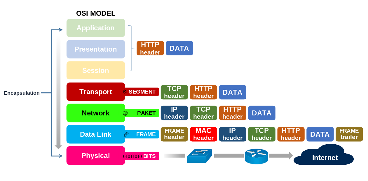
Decapsulation happens at the receiving end, in reverse order, until the application finally gets the original data. Encapsulation allows layer independence: IP doesn’t care whether the lower layer is Ethernet, Wi-Fi, or something else — the IP packet stays the same. This is why IP is so powerful: it provides a universal method of addressing and delivery, while the underlying technology just acts as a “carrier.”
Fragmentation and reassembly
If a packet is larger than what a network supports (MTU), IP can split it into smaller fragments. The destination reassembles them. When data is sent across a network, it travels inside packets. But not every network can handle the same maximum packet size. This maximum size is called the MTU (Maximum Transmission Unit). For example:
- An Ethernet network typically supports an MTU of 1500 bytes.
- A different link type (like PPP or a VPN tunnel) might have a smaller MTU.
If a packet is larger than the MTU of the next link, IP must break it into smaller pieces. This process is called fragmentation.
Fragmentation Process
- The original packet is divided into smaller chunks.
- Each fragment gets its own IP header.
- The header contains fields like:
- Identification → a unique number to mark all fragments of the same packet.
- Fragment Offset → tells the receiver where this piece belongs in the original data.
- More Fragments (MF) Flag → indicates if more pieces are still coming.
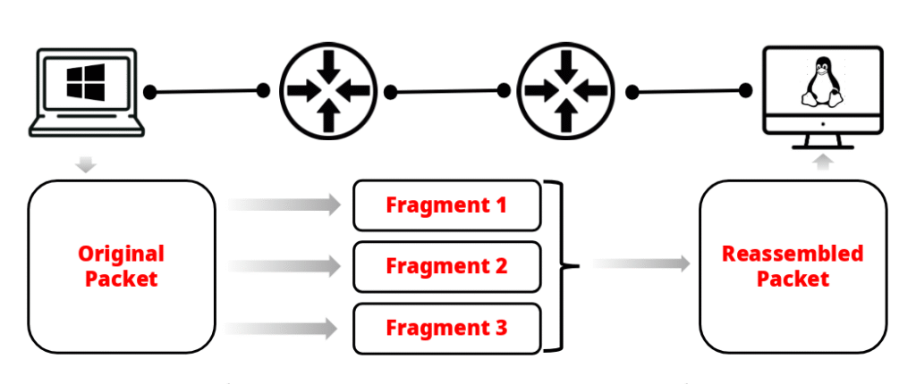
Reassembly at the Destination
- The destination host collects all fragments with the same Identification number.
- Using the Fragment Offset, it reorders the pieces.
- When the last fragment arrives (MF flag = 0), the host reassembles them back into the original packet.
IPv6 handles this differently: routers never fragment packets — only the sending host can do it. Routers generally avoid fragmentation because it’s resource-intensive. Instead, networks rely on Path MTU Discovery (PMTUD) to prevent packets from being too large in the first place. If fragments are lost, the entire packet must be retransmitted (handled by higher-level protocols like TCP).
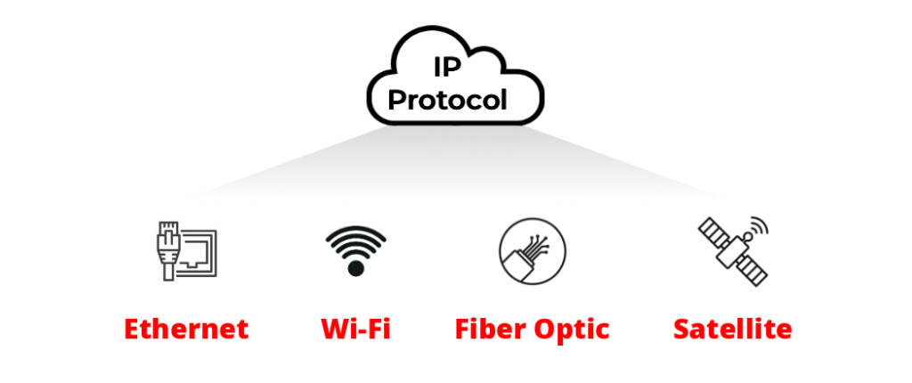
Independent of physical medium
IP works over Ethernet, fiber, Wi-Fi, DSL, or any technology. It doesn’t depend on the physical medium. One of the most powerful aspects of Internet Protocol (IP) is that it is media-independent. In other words, IP does not care how the bits travel across the network — it only cares about addressing and delivering packets.
- Ethernet? Works fine.
- Fiber optics? No problem.
- Wi-Fi radio waves? Perfect.
- DSL or coaxial cables? Works the same.
- Satellite links, 5G, Bluetooth transport tunnels? Still IP.
This works because of the layered architecture of networking. IP operates at Layer 3 (Network Layer) of the OSI model (or the Internet Layer of the TCP/IP model). Below it, at Layer 2 (Data Link Layer), different technologies handle how data is framed and transmitted over their specific physical media:
- Ethernet uses MAC addresses and frames.
- Wi-Fi uses wireless frames with its own headers.
- DSL encapsulates data differently again.
No matter what, when these Layer 2 frames carry an IP packet, the IP header remains unchanged. That’s the key: IP is decoupled from the physical transport.
Why It Matters (CCNA perspective)
Consistency: Devices, routing, and addressing remain the same regardless of the underlying Layer 1 or Layer 2 technology.
Scalability: The Internet can grow globally because IP doesn’t have to be redesigned every time a new medium (like 5G or fiber) is invented.
Interoperability: You can send a packet from a Wi-Fi device, across Ethernet, through a fiber backbone, and out to a DSL home — and IP works seamlessly end to end.
Stateless protocol
Routers do not track packet sessions. Each packet is treated as new, even if it belongs to the same stream of data. One of the defining characteristics of the Internet Protocol (IP) is that it is stateless. This means that routers and other Layer 3 devices do not keep track of ongoing packet sessions.
Implication for Reliability
Because IP doesn’t track sessions, it cannot guarantee delivery order, detect duplicates, or retransmit lost packets. These responsibilities are pushed to higher-layer protocols, such as TCP, which do keep track of streams and provide reliability.
Independent Packets
Every IP packet is processed individually. A router looks only at the packet’s destination IP address, consults its routing table, and forwards the packet toward the next hop.
No Memory of Streams
Even if several packets belong to the same data stream (for example, a video call or a file download), the router does not recognize them as part of a “flow.” Each one is handled as if it were a completely new and unrelated packet.
Efficiency and Scale
This stateless behavior makes IP highly scalable, since routers don’t need to store information about millions of ongoing conversations. Instead, they only maintain a routing table and apply the same forwarding logic to every incoming packet.
Supports multiple versions
IPv4
- Size: IPv4 uses 32-bit addresses.
- Total addresses: 2³² = 4,294,967,296 (~4.3 billion) possible unique addresses.
- Format: Written in dotted decimal notation, divided into four octets (e.g.,
192.168.1.1). - Limitations:
- When IPv4 was designed, 4.3 billion addresses seemed enormous. But with the explosive growth of the Internet, these addresses have been nearly exhausted.
- Workarounds such as NAT (Network Address Translation), private IP ranges, and CIDR (Classless Inter-Domain Routing) were introduced to extend IPv4’s lifetime.
IPv6
- Size: IPv6 uses 128-bit addresses.
- Total addresses: 2¹²⁸ = 340 undecillion addresses (that’s 340 trillion trillion trillion!). For perspective, that’s enough to give every grain of sand on Earth its own unique IP address… and still have plenty left over.
- Format: Written in hexadecimal notation, separated by colons (e.g.,
2001:0db8:85a3::8a2e:0370:7334). - Advantages:
- Virtually unlimited addresses — solving IPv4 exhaustion.
- Built-in security (IPSec) support.
- Simpler header format for more efficient processing.
- No need for NAT — every device can have a globally unique IP.
- Better support for mobile devices and IoT (Internet of Things).
Protocol identification
The IP header includes a field that indicates which transport protocol is inside (TCP, UDP, ICMP, etc.). Inside every IP packet, there’s a section called the IP header. One of the most important pieces of information in this header is the Protocol field.
Relation to OSI model:
This is the point where the Network Layer (IP) interacts with the Transport Layer (TCP/UDP). It’s the “handoff” that makes layered communication possible. The Protocol field tells the receiving device what type of data is inside the IP packet so it knows which upper-layer protocol should handle it. Examples of values: Each protocol is identified by a number (assigned by IANA). For example:
1→ ICMP (used for error messages and tools like ping).6→ TCP (connection-oriented, reliable delivery).17→ UDP (fast, connectionless, used for streaming, DNS, etc.).
Without this field, the receiving host would have no idea how to interpret the data. It would be like receiving a sealed box with no label — you wouldn’t know whether it contains books, clothes, or electronics. The Protocol field is the label.
How it works in practice:
- A packet arrives at a host.
- The host looks at the IP header and checks the Protocol field.
- If the value is
6, the data is passed to the TCP process. - If the value is
17, the data is passed to the UDP process, and so on.
TTL (Time to Live)
Every packet has a TTL value to prevent it from looping forever. Each router decreases TTL by 1, and the packet is discarded when TTL reaches 0.
What it is:
- TTL (Time To Live) is an 8-bit field in the IP header.
- Its purpose is to limit the lifespan of a packet on the network.
- Without TTL, a misconfigured routing table or a loop in the network could cause a packet to circle endlessly, consuming bandwidth and clogging routers.
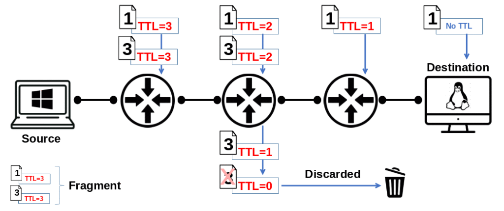
How it works:
- When a packet is created (for example, by your computer sending data), the source host sets an initial TTL value.
- Common defaults: 64 (Linux/Unix), 128 (Windows), or 255 (some Cisco devices).
- Each time the packet passes through a router (a hop), the router decreases the TTL value by 1.
- If the TTL is still greater than 0, the packet is forwarded.
- If the TTL reaches 0, the router discards the packet and sends back an ICMP “Time Exceeded” message to the sender.
Note:
The TTL (Time To Live) field in the IPv4 header is removed when the packet reaches the destination host.

Why:
The purpose of TTL is not to control the packet’s lifetime at the end host, but to prevent packets from looping endlessly in the network.
Each router that forwards the packet decreases the TTL by 1.
If TTL reaches 0 at an intermediate router, that router drops the packet and sends an ICMP Time Exceeded message back to the source.
If the packet successfully arrives at the destination host, the TTL is no longer needed. The destination host processes the packet and then discards the IP header, including the TTL field.
Why it matters:
- Loop prevention: Keeps packets from circulating forever due to routing errors.
- Network troubleshooting: Tools like traceroute rely on TTL. They deliberately send packets with increasing TTL values (1, 2, 3 …). Each router along the path returns an ICMP message when TTL expires, revealing the route step by step.
- Security & fingerprinting: Different operating systems use different default TTL values. Analyzing TTLs can help identify the type of system or detect spoofed packets.
Checksum for header
IPv4 includes a header checksum to detect errors in the IP header (not in the data payload). IPv6 removes this to improve efficiency.
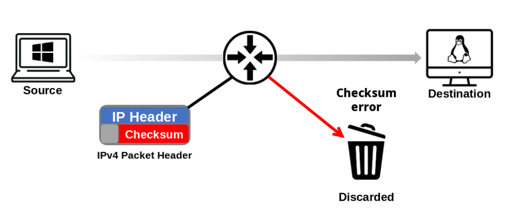
IPv4 Header Checksum: In IPv4, each packet has a header checksum field.
- Its job is to detect errors that might occur in the IP header during transmission.
- For example, if a single bit flips due to noise on the line, the checksum won’t match, and the packet will be discarded.
- Important: this checksum only validates the header, not the data payload. Integrity of the payload is handled by higher-layer protocols like TCP (which has its own checksum).
Every router that forwards the packet recalculates the checksum, because the header changes along the way (e.g., TTL decreases by 1 at each hop). This constant recalculation adds extra processing overhead at each router.
IPv6 Removes the Header Checksum: When IPv6 was designed, engineers decided to remove the header checksum entirely. Why?
- Efficiency: Routers no longer waste CPU cycles recalculating checksums for every packet at every hop. This speeds up packet forwarding significantly.
- Redundancy: Error detection is already handled at other layers:
- Data Link Layer → Frame Check Sequence (Ethernet FCS, CRC checks).
- Transport Layer → TCP/UDP checksums for payload integrity.
- Application Layer → Some protocols add their own error detection (e.g., HTTPS with TLS).
- Simplification: IPv6 headers were designed to be more streamlined and less resource-intensive, improving scalability for high-speed networks.
Key Difference (Exam Tip)
IPv4 → Has a header checksum (must be recalculated at every hop).
IPv6 → No header checksum (relies on lower and upper layers for error detection, which is more efficient).
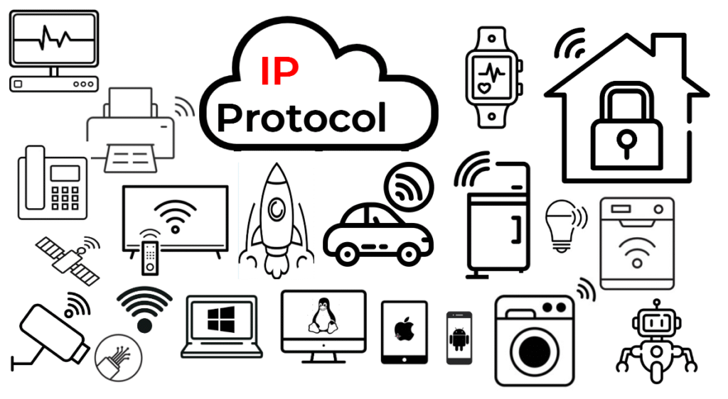
Universal standard
IP is the foundation of all modern networking. All devices, regardless of brand or type, use IP to communicate over the Internet. Internet Protocol (IP) is the core building block of all modern networking. At its heart, IP provides a common language that allows devices to communicate, no matter their manufacturer, operating system, or type of hardware.
- Addressing and Routing: At its core, IP gives each device a unique address and provides the rules for forwarding packets from one network to another, ensuring data can move from any origin to any destination.
- Universality: Every smartphone, laptop, router, smart TV, or industrial sensor that connects to the Internet relies on IP. Whether it’s Apple, Cisco, Huawei, or Dell, they all “speak” IP.
- Interoperability: Because IP is a standardized protocol, different technologies can coexist and interact. A Windows PC can send data to a Linux server; an Android phone can stream from a camera built by a completely different vendor.
- Scalability: IP isn’t just for small home networks. The same rules apply to the largest enterprise backbones and the global Internet, making it infinitely scalable.
- Independence from Media: IP doesn’t care if it runs over fiber, Wi-Fi, 5G, or satellite. It only requires an underlying transport that can carry its packets.
When you think of IP, think of it as the foundation layer that everything else depends on. Protocols like HTTP, DNS, or email are all useless without IP underneath. It is the universal “glue” of the Internet, ensuring that billions of devices can talk to each other reliably.
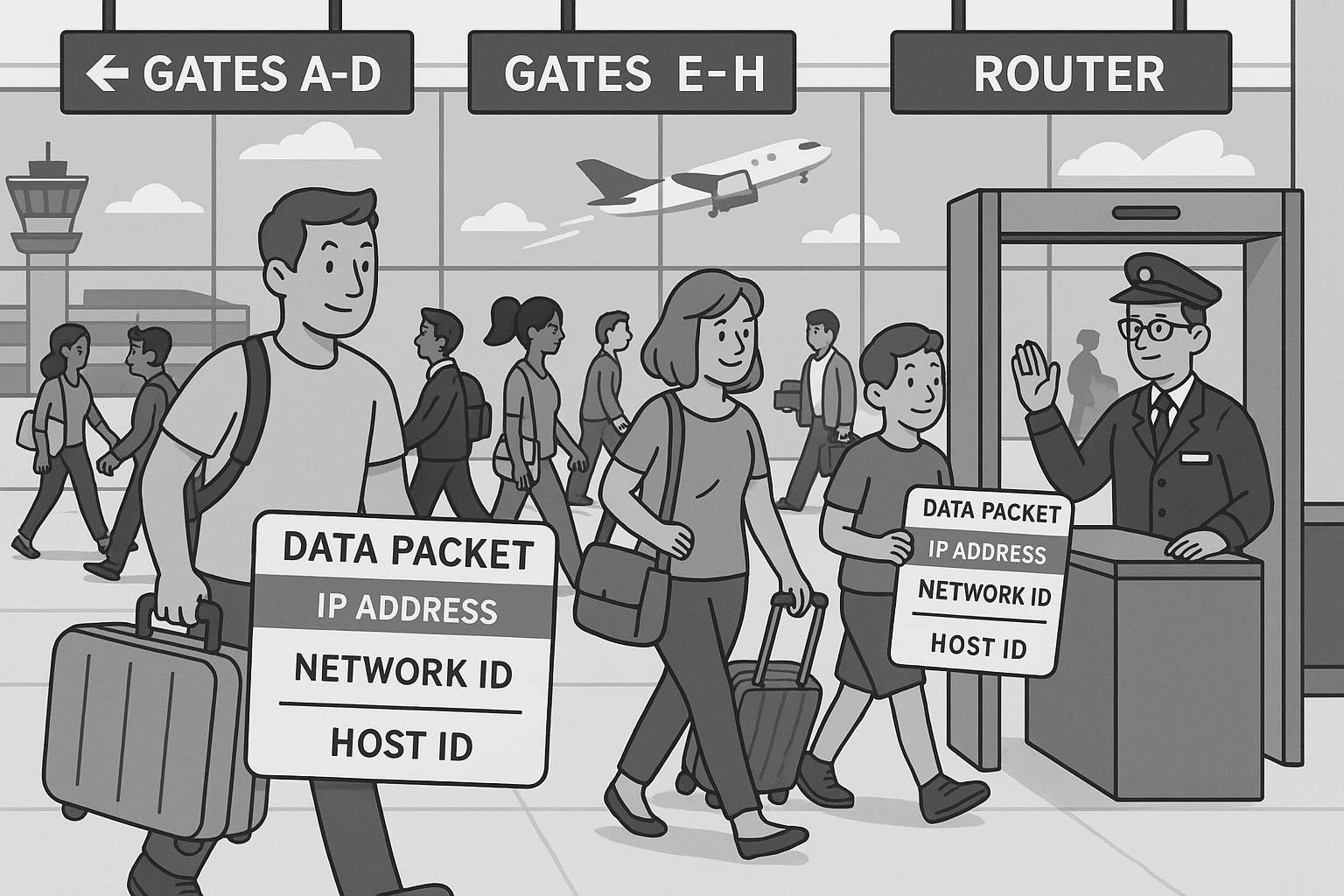
Understanding Internet Protocol (IP): The Airport Journey
Imagine you are at a busy international airport, preparing for a long trip. Travelers are rushing in every direction, flights are departing constantly, and thousands of people need to be moved smoothly from one place to another. This is how Internet Protocol (IP) works behind the scenes.
Each traveler in the airport represents a data packet. Some travelers may be part of the same family, just as some packets belong to the same file or video. But once inside the airport, each traveler moves through the system independently.
Every traveler carries a boarding pass, which acts like an IP address. The boarding pass contains two key pieces of information:
- The destination airport (the network ID).
- The seat number on the plane (the host ID).
As you make your way through the airport, you pass through several checkpoints — security, customs, boarding gates. Each checkpoint functions like a router. The staff don’t escort you personally or track your whole journey. They simply glance at your boarding pass, decide the correct direction, and wave you forward. In networking, that’s exactly what routers do with packets.
But just like IP, the airport system operates on a best-effort basis. Most of the time, you and your luggage make it safely to the destination. But sometimes, bags get delayed, connections are missed, or passengers arrive out of order. The system does its best but makes no promises — higher systems, like TCP in networking, take care of fixing those problems.
Now imagine your suitcase is too large for the overhead bin. The airline splits it into parts: one piece travels with you as carry-on, the other goes in the cargo hold. At your destination, you reunite the pieces. This is just like fragmentation and reassembly in IP.
There’s also a limit to how long you can stay in the system. Your boarding pass is only valid for a certain date and time. If you try to travel after it has expired, you won’t be allowed to continue. This is what IP does with the Time To Live (TTL) value — ensuring packets don’t wander the Internet forever.
Finally, it’s important to note that each checkpoint you pass is stateless. The staff at security or customs don’t remember you from earlier in the journey. Each time, they look at your boarding pass as if they’re seeing you for the first time. That’s exactly how routers treat IP packets.
In the end, Internet Protocol works like the invisible logistics system of global air travel. It doesn’t guarantee perfection, and it doesn’t personally escort each packet to its destination. But it provides the rules and mechanisms that allow millions of packets — like millions of passengers — to move independently and still reach the right destination most of the time.
Outline
Packets as Passengers: Every passenger is like a data packet. Families may travel together (like packets from the same file), but each moves independently.

IP Address as Boarding Pass: A boarding pass shows the **destination airport (network ID)** and **seat number (host ID)**.

Routers as Checkpoints: At security or customs, staff scan your pass, point you forward, and let you go. They don’t remember you afterward.

Best Effort: Most flights succeed, but luggage may be lost, flights delayed, or passengers arrive out of order. The system tries, but doesn’t guarantee.

Fragmentation: Oversized luggage may be split into smaller pieces for transport and later reassembled at the destination.

TTL: Boarding passes expire after a set time, just like packets with a Time To Live.

Stateless Processing: Each checkpoint treats you like a new passenger, every time.
CCNA Exam Tip:
Remember the three big IP traits
Connectionless (no session setup),
Best-effort (no guarantees),
Stateless (no tracking of packets).
Those are test favorites…
Summary
What Did You Learn Today?
Let’s Find Out!
Instructions
- Select the correct answer for each technology concept.
- All questions pertain directly to the networking technologies explained.
- After answering, click “See Result” to see your score and feedback.
[Return to CCNA Study Hub] — Next Stop: [Section 2 | Decimal and Binary Explained] …Currently Buffering… Available Soon!