
Beginner’s Guide to the TCP/IP Link Layer
Where every network conversation begins
First Listen: let your ears lead the way before your mind takes notes.
📻 FZ2CCNA Radio:
Then read: let your eyes explore before your mind starts to explain.
From Zero to Connectivity: The Link Layer
If the internet were a huge city, the Link Layer would be the sidewalks, roads, and traffic lights that keep everything moving at street level. Before data can rocket across continents or beam through satellites, it first has to figure out how to get from one device to another right next door—and that’s exactly the Link Layer’s job.
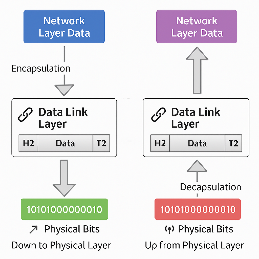
This is the ground floor of networking, the layer that takes raw bits (zeros and ones) and makes sure they don’t just vanish into the void. Instead, it gives those bits a ride across cables, fiber, or Wi-Fi, wrapping them in neat “frames,” tagging them with addresses, and handing them to the right device.
In this guide, we’ll walk step-by-step through the essentials of the Link Layer. We’ll keep it simple, fun, and very visual—so even if you’ve never touched a network cable in your life, you’ll leave with a solid foundation.
How Devices Talk: Network Communication Modes
Think of a LAN (Local Area Network) like a group chat. Depending on how you want to share your message, you can:
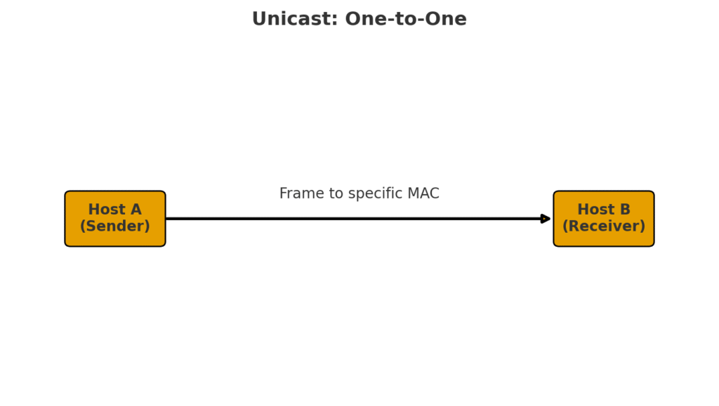
- Unicast – Send a message to just one friend in the group. (Like texting only Sarah about tonight’s dinner.)
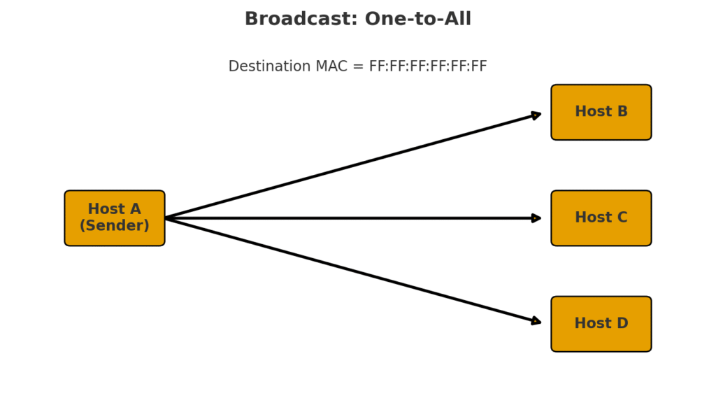
- Broadcast – Shout a message to everyone in the chat. (Like saying “Who wants pizza?” and suddenly 10 people respond.)
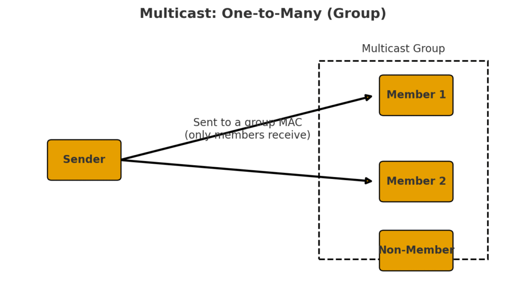
- Multicast – Whisper to only a specific set of friends. (Like sharing memes only with your gamer buddies, not your boss.)
- Anycast – Send a message to the nearest friend out of a group who could answer. (Like texting all the pizza places in town at once, but only the closest one replies with “On my way!”)
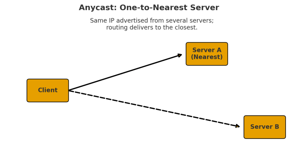
These four styles are the foundation of how communication happens inside a LAN. Without them, devices would either talk over each other or not know who the message was for.
The Roads of Ethernet: Cables, Connectors, and PoE in Networking
When we think about plugging a switch into a network, it might look as simple as connecting a cable from one box to another. But behind that “click” of an Ethernet cable going into a port is a world of standards, rules, and engineering genius that make modern networking possible. Let’s unpack Ethernet — the superstar of LAN communication.
Ethernet: More Than Just a Cable
Most people, when they hear the word Ethernet, immediately think of the blue (or sometimes yellow) cable lying around the office or behind the TV. But Ethernet is not just a cable. It’s a networking standard — a set of guidelines created by the IEEE (Institute of Electrical and Electronics Engineers).
The official name of this standard is IEEE 802.3. In practice, “Ethernet” and “IEEE 802.3” are often used interchangeably, although technically IEEE 802.3 refers to the formal document and its detailed specifications, while Ethernet is the more common, everyday term.
Think of Ethernet as the “rulebook” that ensures computers, switches, routers, and cables can all understand each other — no matter the manufacturer.
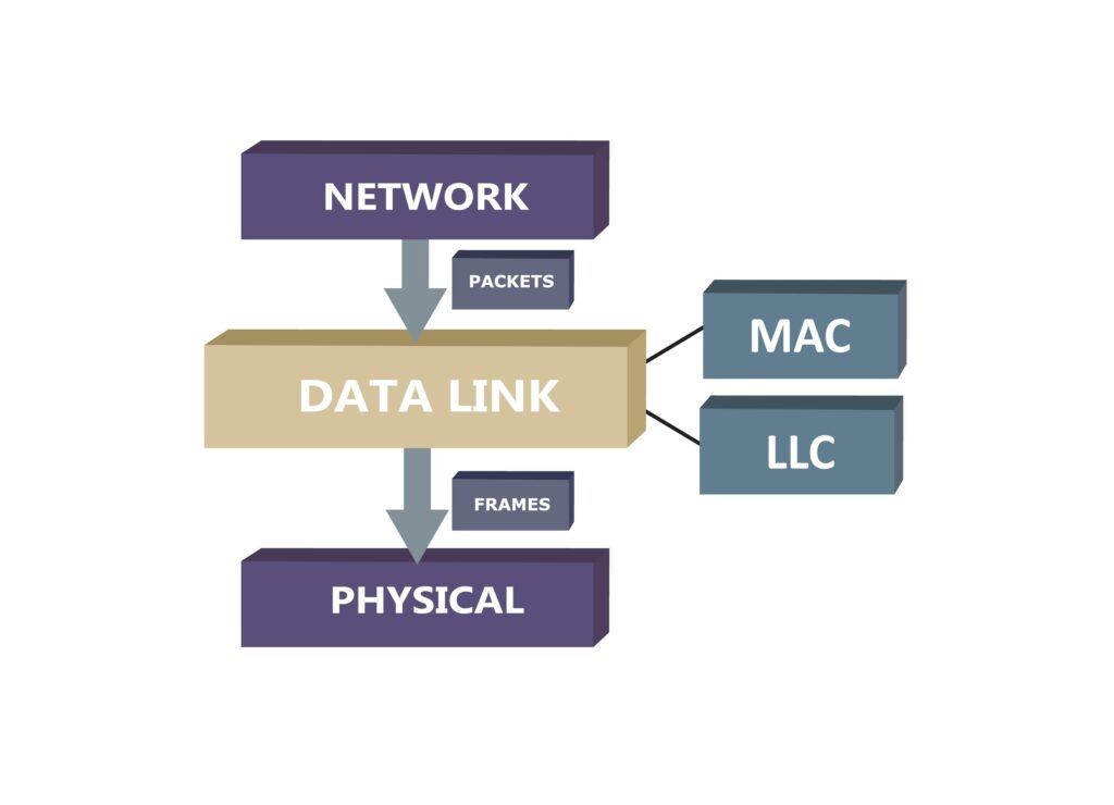
Ethernet’s Role: The Physical and Data Link Layers Explained
Layer 1: The Road: The Physical Layer is like the road your packages travel on. It doesn’t care what’s inside the package; it just makes sure the road is built correctly. Here, Ethernet defines the physical aspects:
- The Cables: It specifies the type of cable (like network cables with RJ45 connectors) that should be used.
- The Signals: It defines how binary data (ones and zeros) are encoded into electrical or light pulses so they can travel across the cable.
In short, Ethernet’s Layer 1 ensures there is a physical connection for data to move.
Layer 2: The Traffic Rules: The Data Link Layer is like the traffic rules that prevent accidents on the road. It makes sure that data from one device reaches the correct device on the same local network. Here, Ethernet sets the rules:
- MAC Addresses: It assigns each device a MAC address (Media Access Control), which is like a car’s license plate. This allows the packet to reach its exact destination on the local network.
- Frames: It packages the data into “frames,” which are like envelopes that contain the information and the source and destination addresses. These frames travel across the network in an organized way.
Ethernet is the standard that defines both the physical infrastructure (cables, radio waves and connectors) and the set of rules (addresses and frames) for devices to communicate reliably on a local network.
Now that we know how messages could be sent, let’s look at how they actually travel. Data needs a path, and that path comes in different flavors:
- Copper cables (twisted pair) – Think of these as the local roads of networking. Cheap, flexible, and great for short distances like inside an office.
- Fiber optic cables – Highways for data. Instead of using electricity, they use light. Fast, long-distance, and shiny (literally).
- Wireless (Wi-Fi) – The air routes. No cables needed, but like airports, they can get crowded if too many “planes” (devices) are flying at once.
In CCNA world, remember: copper = common, fiber = fast and far, wireless = flexible but tricky.
Ethernet Standards: Decoding the Names
Here’s where it gets fun: the cryptic names like 1000BASE-T aren’t random gibberish. Each part of the name has meaning:
- 1000 → The speed in Mbps. So, 1000 means 1000 Megabits per second (a.k.a. 1 Gbps).
- BASE → Baseband signaling, which means only Ethernet traffic runs on the cable (as opposed to broadband, where multiple signals share the same medium).
- T → The type of cabling used. In this case, “T” stands for twisted-pair cables (the most common Ethernet cables you see).
Let’s look at a few popular examples:
- 10BASE-T → 10 Mbps over twisted-pair cable. Old school, but still around in legacy systems.
- 100BASE-TX → 100 Mbps over twisted-pair cable. The “Fast Ethernet” era.
- 1000BASE-T → 1 Gbps over twisted-pair cable. Common in homes and offices today.
- 10GBASE-SR → 10 Gbps using short-range fiber optics.
It’s like a secret code: once you learn to read it, you can instantly tell what speed, signal type, and cable a standard uses.
Twisted-Pair Cabling: The Everyday Hero
When you connect a switch to a LAN, chances are you’re using twisted-pair Ethernet cabling — also called UTP (Unshielded Twisted Pair).
But why twist the wires?
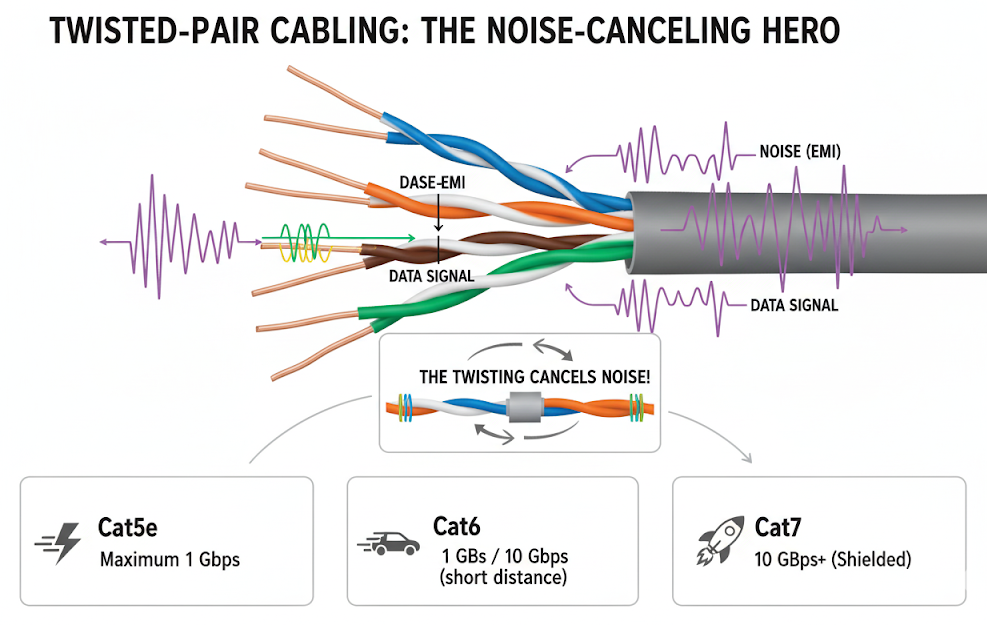
Because when two wires are twisted together, the electromagnetic interference (EMI) they pick up from outside sources tends to cancel out. Think of it like two friends whispering secrets in a noisy cafeteria — by leaning in close and speaking in sync, they can hear each other even when the room is chaotic.
There are different categories of twisted-pair cables, each supporting different speeds:
- Cat5e: Supports up to 1 Gbps. Common in older installations.
- Cat6: Supports 1 Gbps and can handle 10 Gbps over short distances.
- Cat6a and Cat7: Better shielding, supporting faster speeds over longer runs.
Twisted-pair is inexpensive, flexible, and reliable — which is why it’s the workhorse of LANs worldwide.
Ethernet Cabling Standards
| Standard | Media | Max Segment Length | Connector | Notes / Memory Hook |
|---|---|---|---|---|
| 100BASE-TX | Cat 5 UTP (2 pairs) | 100 m (328 ft) | RJ-45 (ISO 8877) | TX = Twisted Pair (Copper) |
| 100BASE-FX | 62.5/125 multimode fiber | 400 m (1312 ft) | Duplex MIC ST | FX = Fiber Fast Ethernet |
| 1000BASE-T | Cat 5/5e UTP (4 pairs) | 100 m (328 ft) | RJ-45 (ISO 8877) | Gigabit over Copper |
| 1000BASE-SX | 62.5/50 multimode fiber | 275 m (62.5 µm) / 550 m (50 µm) | Optical fiber connector | SX = Short fiber |
| 1000BASE-LX | 9 single-mode fiber | 5–10 km (1.86–6.2 miles) | Optical fiber connector | LX = Long fiber |
Tips for Memorizing“
- TX → Twisted Pair (cobre, 100 m).
- FX → Fiber Fast Ethernet (400 m).
- SX → Short fiber (hasta ~500 m).
- LX → Long fiber (hasta 10 km).
| Ethernet Medium | Description | Typical Use | Pros | Cons |
|---|---|---|---|---|
| Coaxial Cable (Legacy) | Original medium for Ethernet (10BASE-2, 10BASE-5). Shared bus topology where all devices tapped into the same cable. | Obsolete today; replaced by twisted pair and fiber. | Durable, decent shielding against interference. | Bulky, hard to install, limited speed (10 Mbps), not scalable. |
| Twisted Pair Copper (UTP/STP) | Most common medium today. Pairs of wires twisted to reduce EMI. Standards like Cat5e, Cat6, Cat6a, Cat7. | LAN connections (PCs, switches, routers, etc.). | Cheap, flexible, easy to install, supports up to 10 Gbps (Cat6a). | Limited distance (100m per segment), susceptible to EMI without shielding. |
| Fiber Optic Cable | Uses light signals through glass or plastic fiber. Variants: single-mode (long distance) and multi-mode (shorter distance). | High-speed backbones, data centers, WAN links. | Very high bandwidth (100 Gbps+), long distance, immune to EMI. | More expensive, fragile, requires special installation and connectors. |
Key takeaway:
- Coaxial = history lesson
- Twisted pair = your everyday LAN hero
- Fiber optic = the Formula 1 racecar of networking
Copper Media (Network Cables)
When you plug your computer into a switch with that classic blue cable (or yellow, or bright green), chances are you’re using UTP.
This type of cable is cheap, easy to install, and works great for short and medium distances (up to 100 meters).
Unshielded Twisted-Pair (UTP)
Here’s the trick: inside that blue cable, there aren’t just one or two wires — there are 8 tiny copper wires.
And they’re not straight — they’re twisted together in pairs (that’s where the “Twisted Pair” name comes from).
But why twist them like shoelaces?
To protect the signal.
When two wires are twisted together, the electrical noise they pick up from outside sources cancels out.
Think of two friends whispering in a noisy party: even with all the background chaos, they can still understand each other.
Advantages of UTP
- Low cost: way cheaper than fiber.
- Easy to install: bends without breaking and not fragile.
- Distance limit: up to 100 meters per run before the signal starts to fade.
- Fast speeds: depends on the cable category (Cat5e, Cat6, Cat6a, etc.).
Shielded Twisted-Pair (STP)
You know that clever trick with the twisted wires? STP takes it to the next level. Inside that cable, you’ll find the same 8 tiny copper wires, meticulously twisted into pairs (that’s the “Twisted-Pair” part we know and love). But here’s the upgrade: each pair (or sometimes the whole bundle) gets wrapped in a special metallic foil shield. And often, there’s an extra braided metal mesh surrounding everything inside the jacket.
So why the suit of armor?
For ultimate protection. While the twists cancel out general noise, the added shielding creates a barrier against powerful electromagnetic interference (EMI). Think of massive machinery, powerful motors, or large bundles of cables running alongside each other.
Imagine those two friends whispering at that noisy party, but now they’re also inside a soundproof booth. The twisting lets them hear each other clearly, and the booth blocks out the deafening roar of the crowd and the band. That’s STP.
Key takeaway
UTP is the everyday hero of modern networks. If you’ve ever used an Ethernet cable at home or at work, it was almost certainly UTP.
The Silent Architecture of Ethernet: Twists, Pairs, and Performance
When people think of networking, they picture glowing data centers and wireless signals flying through the air. Yet, most of the world’s digital traffic still depends on something far more ordinary: a copper cable, carefully twisted into pairs. Ethernet over twisted-pair isn’t flashy, but it’s the reason your office, your home, and entire enterprises can connect at high speed with surprising reliability.
Why the Twist Matters
If you lay two copper wires side by side, they quickly become antennas. They’ll absorb interference from fluorescent lights, motors, radio signals, or even other nearby cables. The solution engineers found wasn’t more shielding or bulk—it was geometry.
By twisting the wires, each conductor is exposed equally to external noise. Over the length of the cable, these disturbances cancel each other out. It’s not decoration; it’s physics in action. The tighter and more carefully engineered the twist, the less vulnerable the cable is to electromagnetic interference (EMI) and crosstalk.
The Structure of UTP Cabling
Unshielded Twisted Pair (UTP) cabling looks modest from the outside, but inside it follows strict design rules:
- Four pairs of copper wires → eight conductors in total.
- Each pair has its own twist rate, precisely measured and varied from pair to pair. This prevents interference between the pairs themselves.
- 22–24 gauge copper → thick enough to carry signals, thin enough to remain flexible.
- 100-ohm impedance → a defining electrical characteristic that distinguishes network cabling from telephone wiring.
- Outer diameter ~0.43 cm → small enough to bundle by the hundreds in structured cabling installations.
The result is a medium that is cost-effective, reliable, and easy to deploy in both small offices and massive enterprise networks.
Categories: A Timeline of Progress
UTP cabling has been standardized into categories, each iteration supporting higher bandwidths and stricter performance requirements. Think of them as milestones in networking’s evolution.
| Category | Speed & Distance | Key Features | Current Use |
|---|---|---|---|
| Cat 5 | 100 Mbps | Introduced the modern standard for Fast Ethernet | Obsolete |
| Cat 5e | 1 Gbps | Enhanced Cat 5, backward compatible | Still common in existing networks |
| Cat 6 | 10 Gbps (up to 55m) | Great for new installations | Widely used |
| Cat 6a | 10 Gbps (up to 100m) | Improved Cat 6, better shielding | Standard for enterprise cabling |
| Cat 7 | 10 Gbps | Shielded to reduce interference | Used in high-noise/data-heavy environments |
| Cat 8 | Up to 40 Gbps (short distances) | Designed for data centers | Rare outside data centers |
Why UTP Still Dominates
Despite the rise of fiber optics and wireless, UTP remains the backbone of everyday networking because:
- Cost: Copper is cheaper to deploy than fiber for most short to medium distances.
- Flexibility: Easy to terminate, bend, and install without specialized tools.
- Compatibility: Works seamlessly with switches, routers, and NICs across decades of Ethernet standards.
- Performance: With Cat 6 and Cat 6a, most organizations get more than enough bandwidth for daily operations.
Key Points to Remember
- Twisting isn’t random—it’s engineered to cancel interference and crosstalk.
- UTP cabling always has four twisted pairs with slightly different twist rates.
- Impedance of 100 ohms is the hallmark of Ethernet-grade twisted-pair cabling.
- Category upgrades = higher speeds and stricter performance tolerances.
- Cat 6a is the “sweet spot” for most modern enterprise networks; Cat 8 is for data centers.
CCNA Exam Tips
Memorize the speed ladder:
Cat 5 → 100 Mbps
Cat 5e → 1 Gbps
Cat 6 / 6a / 7 → 10 Gbps
Cat 8 → 40 Gbps

Watch for distance limits. Cat 6 at 10 Gbps works only up to ~55 meters. Cat 6a extends it to 100 meters.
Don’t confuse UTP with phone wiring. The 100-ohm impedance is the clear differentiation.
If the question says “modern enterprise standard,” the answer is Cat 6a.
RJ-45 Connector and Jack: The Handshake of Ethernet
Cables are useless unless they have a way to connect. In networking, that magical “handshake” happens through the RJ-45 connector and jack. This small, clicky piece of plastic is so ordinary that we barely notice it—but without it, your Ethernet cable would just be a colorful rope.
Meet the RJ-45 Plug (Male Connector)
The RJ-45 plug is the piece you hold in your hand at the end of a UTP cable. It’s the male component of the pair.
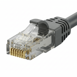
- Construction: Clear plastic body, inside of which are eight tiny gold pins. These pins make the actual electrical contact with the copper wires inside your UTP cable.
- Crimping: To attach it, the cable is stripped, wires are arranged in a specific order (T568A or T568B standard), and then “crimped” into the plug with a special tool. The metal contacts bite into the copper wires, locking everything into place.
- Pin Numbering: If you hold the connector facing you (clip down, gold pins up), the numbering runs from left to right, 8 → 1.
Think of the RJ-45 plug as the key that unlocks the network.
Meet the RJ-45 Jack (Female Connector)
Now for the RJ-45 jack, the counterpart waiting for the plug.
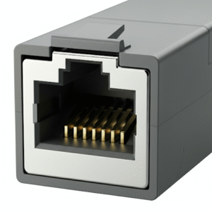
- Location: Found on switches, routers, PCs, wall outlets, patch panels, and pretty much any device that speaks Ethernet.
- Design: A small rectangular slot with spring-loaded contacts that line up perfectly with the plug’s pins.
- Pin Numbering: Facing the jack, the numbering runs from left to right, 1 → 8—the mirror image of the plug.
In other words, when the plug slides into the jack, pin 1 meets pin 1, pin 2 meets pin 2, and so on. The connection is precise, like puzzle pieces snapping together.
Why Eight Pins?
Ethernet over twisted-pair uses four pairs (eight wires). Depending on the Ethernet standard:
- Fast Ethernet (100 Mbps): Uses only two pairs (pins 1–2 and 3–6).
- Gigabit Ethernet (1 Gbps): Uses all four pairs (pins 1–8).
- 10 Gbps and beyond: Also use all four pairs, but with more advanced signaling.
So, those extra pins aren’t decorative—they’re the highways for faster traffic.
Common Uses of RJ-45
- Direct Connections: PC → Switch, Switch → Router.
- Patch Panels: Neatly connecting dozens (or hundreds) of cables in server rooms.
- Wall Outlets: Providing structured cabling in offices so you don’t have loose wires everywhere.
Whenever you hear that satisfying “click” as the plug snaps into the jack, you know a reliable electrical and data path has been established.
Key Points to Remember
- RJ-45 plug = male → crimped to the end of a cable.
- RJ-45 jack = female → embedded in devices or outlets.
- Pin numbering:
- Plug: 8 → 1 (left to right).
- Jack: 1 → 8 (left to right).
- Eight pins = four pairs of wires.
- Ethernet speeds determine how many pairs are actually used.
CCNA Exam Tips
Know your terminology: RJ-45 is the connector; UTP is the cable. Don’t confuse them.
Plug vs. Jack: Male vs. Female. A very common exam question.
Pinouts: T568A and T568B wiring orders matter for crossover vs. straight-through cables.
Legacy reminder: 10/100 Mbps uses only two pairs; Gigabit and above use all four.
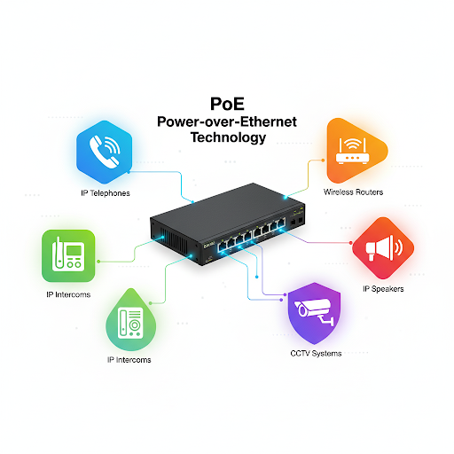
Power over Ethernet (PoE)
Imagine if your phone charger and internet cable could be combined into one — no more messy wires under your desk. That’s basically what Power over Ethernet (PoE) does for networking.
PoE is a technology that allows both electrical power and data to travel over the same Ethernet cable. Instead of needing one cable for power and another for network connectivity, you can plug in just a single Ethernet cable and get both. It’s efficient, neat, and especially handy in places where running separate power lines would be expensive or impractical.
How PoE Works
Normally, Ethernet cables are used only for sending data, like web traffic or video streams. A typical Ethernet cable (Cat5e, Cat6, or higher) has four twisted pairs of wires inside. Traditional data transmission uses only two of these pairs. PoE takes advantage of the unused pairs — or, in newer standards, cleverly injects power into the same pairs that carry data — without interfering with the network signal.
So, your device gets both internet/data signals and electrical power through one cord.
Devices That Benefit from PoE
Think about places where you see networking equipment but don’t see obvious power outlets. PoE is a lifesaver there. Some common examples are:
- Wireless Access Points (WAPs): Instead of drilling holes for new power sockets, you can run just one Ethernet cable through the ceiling.
- IP Cameras (Security Cameras): Perfect for outdoor areas or corners of buildings where running electrical wiring would be a nightmare.
- VoIP Phones: A single cable keeps desks uncluttered while powering the phone and connecting calls.
- IoT Devices & Sensors: Smart devices in offices or factories often rely on PoE for simplicity.
PoE Standards
The Institute of Electrical and Electronics Engineers (IEEE) has defined standards for PoE under 802.3, and these standards basically say how much power you can push through the cable:
- IEEE 802.3af (PoE): Provides up to 15.4 watts of DC power per device. Good for VoIP phones and basic access points.
- IEEE 802.3at (PoE+): Provides up to 30 watts. Useful for more power-hungry wireless access points or pan-tilt-zoom (PTZ) cameras.
- IEEE 802.3bt (PoE++ or 4PPoE): Provides up to 60–100 watts depending on the type. Strong enough for laptops, flat screens, and advanced devices.
The higher the standard, the more powerful devices you can run without needing separate power lines.
Two Sides of PoE: Power Sourcing & Receiving
PoE isn’t magic — you need two ends working together:
- Power Sourcing Equipment (PSE): This is usually a switch that’s PoE-enabled, or sometimes a special injector device. It sends power into the cable.
- Powered Device (PD): This is the gadget that receives power, like an IP camera or VoIP phone.
If your switch doesn’t have built-in PoE, you can use a PoE injector (think of it as a middleman that “injects” power into the line).
Advantages of PoE
- Simplicity: One cable to rule them all — less clutter, easier installation.
- Flexibility: You can install devices in places without nearby power outlets.
- Cost Saving: No need for expensive electrical work or hiring electricians.
- Scalability: Easy to add more devices without worrying about power availability.
Limitations of PoE
Of course, PoE isn’t perfect:
- Distance: Ethernet cables have a max length of 100 meters (328 feet), so PoE devices must stay within that range.
- Power Cap: Not every device can be powered via Ethernet. High-energy devices (like desktop computers) are too demanding.
- Heat: More power in cables can generate heat, which may reduce cable lifespan if not managed properly.
Key Takeaway
Power over Ethernet combines data + power into a single, simple cable. It makes installing network devices cheaper, cleaner, and more flexible — which is why it’s everywhere, from your office VoIP phone to the security cameras in your local coffee shop.
CCNA Exam Tips
Know the IEEE PoE standards: 802.3af (15.4W), 802.3at (30W), 802.3bt (60–100W).
Understand PSE vs. PD (who sends power vs. who receives it).
Remember the 100-meter cable limit still applies.
Recognize common devices that use PoE: WAPs, IP cameras, VoIP phones.
Be aware of PoE injectors as a solution if a switch doesn’t provide PoE.
Straight-Through or Crossover UTP Cable?
When you’re setting up a network, one of the most common questions is: Which type of Ethernet cable should I use? The answer usually comes down to straight-through cables vs crossover cables.
Straight-Through Cable
- Definition: Both ends of the cable are wired the same way. Pin 1 goes to Pin 1, Pin 2 goes to Pin 2, and so on.
- Purpose: Used to connect different types of devices.
- Examples:
- Switch ↔ Router
- Switch ↔ PC
- Switch ↔ Server
Think of it like a normal conversation between two people: one speaks, the other listens.
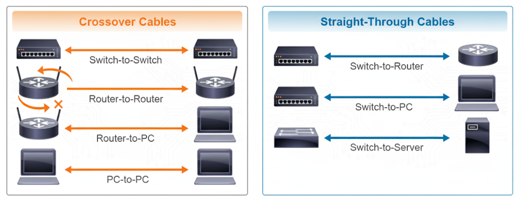
Crossover Cable
- Definition: Some wires swap places. Specifically, the transmit pins on one end connect to the receive pins on the other.
- Purpose: Used to connect similar devices.
- Examples:
- Switch ↔ Switch
- Router ↔ Router
- PC ↔ PC
- Router ↔ PC
It’s like two people who both start talking at the same time — one of them needs to “switch roles” to listen, otherwise, nobody understands anything.
How to Tell Them Apart
- Hold both connectors side by side with the pins facing you.
- If the wire order looks the same on both ends → Straight-through.
- If some wires are crossed/swapped → Crossover.
The Legacy Note (Why You Rarely Need Crossovers Now)
In the old days, choosing the right cable was crucial. Use the wrong one, and your devices simply wouldn’t talk.
Today, most modern devices (switches, routers, PCs) support a feature called auto-MDIX. This means the device automatically detects whether the connection needs a crossover or straight-through — and adjusts internally.
Translation: You can use a straight-through cable almost everywhere, and the device will fix the rest.
Quick Summary
- Straight-through: Different devices (Switch–PC, Switch–Router).
- Crossover: Same devices (Switch–Switch, PC–PC, Router–Router).
- Auto-MDIX: Makes crossover cables mostly obsolete.
CCNA Exam Tip
Remember the phrase:
Straight-through → unlike devices.
Crossover → like devices.

Auto-MDIX is often tested, so don’t forget it “auto-magically” fixes cabling issues.
Fiber Optics: The Speed of Light in Your Network
When you think of the internet, you might imagine Wi-Fi waves floating through the air or rows of Ethernet cables plugged into computers. But behind the scenes, the real superstar of modern connectivity is something far thinner and shinier: optical fiber.
Fiber optics is like the superhero nobody sees. Made of glass thinner than a human hair, it silently carries the world’s data across oceans, cities, and homes—all at the speed of light. Without it, there would be no Netflix marathons, no smooth Zoom meetings, and no TikTok rabbit holes at 2 a.m.
In this article, we’ll break fiber optics down step by step: what it is, how it works, why it beats copper cables, and the key details you’ll need for your CCNA exam.
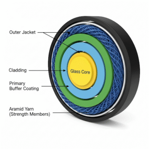
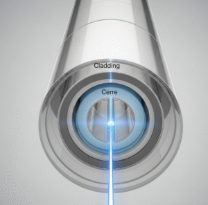
The Anatomy of a Fiber-Optic Cable
An optical fiber looks delicate, but its structure is both brilliant and practical. Think of it as a layered candy:
- Core: This is the gooey caramel center. It’s made of ultra-pure glass, and this is where the light signal actually travels.
- Cladding: The candy shell. It surrounds the core and reflects the light back in, making sure the signal doesn’t escape. This reflection happens thanks to a principle called total internal reflection.
- Coating or Buffer: This is the protective wrapper. A plastic layer that shields the fragile glass from scratches, moisture, and clumsy technicians dropping tools on it.
That’s the magic: a hair-thin piece of glass that can send data across continents.
How Light Travels Through Fiber
Here’s where it gets really cool. Data in fiber doesn’t move as electricity (like in copper). Instead, it’s sent as pulses of light—tiny flashes, like Morse code but super fast.
Depending on how the fiber is designed, the light can either take one perfect path or bounce around like kids in a playground. That leads us to the two main types of fiber.
Multimode Fiber (MMF)
Picture a wide highway with many lanes. Cars (light pulses) zoom in all directions, taking different paths to reach the same destination. That’s multimode fiber.
- Core size: Larger (about 50–62.5 microns).
- Light source: Inexpensive LEDs.
- Best for: Short distances, like inside a building or data center.
- Speed & distance: Fast (10 Gbps and beyond) but only up to a few hundred meters.
- Downside: Because the signals take different paths, they can arrive at slightly different times, causing modal dispersion (think of people arriving late to a party).
Single-Mode Fiber (SMF)
Now swap the highway for a bullet train track. Only one precise path, one destination, no bouncing around. That’s single-mode fiber.
- Core size: Tiny (about 8–10 microns).
- Light source: Powerful lasers.
- Best for: Long-distance communication—connecting campuses, cities, or even continents.
- Speed & distance: Can carry data at blazing speeds over 30–100 km without needing repeaters.
- Upside: No dispersion issues, because there’s only one path.
Fiber vs. Copper: The Showdown
Copper cables are like the reliable old pickup truck: cheap, tough, and good for short trips. Fiber optics, on the other hand, is a high-speed sports car: faster, sleeker, and built for long runs.
Here’s the comparison:
| Feature | Copper (UTP) | Fiber Optic |
|---|---|---|
| Signal type | Electricity | Pulses of light |
| Max distance | ~100 meters (Cat 5e/6) | 30+ km for single-mode |
| Speed/Bandwidth | Lower | Extremely high |
| Interference (EMI) | Vulnerable to noise | Immune to EMI |
| Security | Easy to tap | Very hard to tap |
| Cost | Cheaper upfront | More expensive initially |
Key takeaway: Use copper for short desktop connections, but rely on fiber for backbone networks and high-speed, long-distance communication.
Fiber Connectors: The Plugs That Make It Work
Unlike your regular RJ-45 Ethernet cable, fiber connectors come in different shapes and sizes. Some of the most common are:
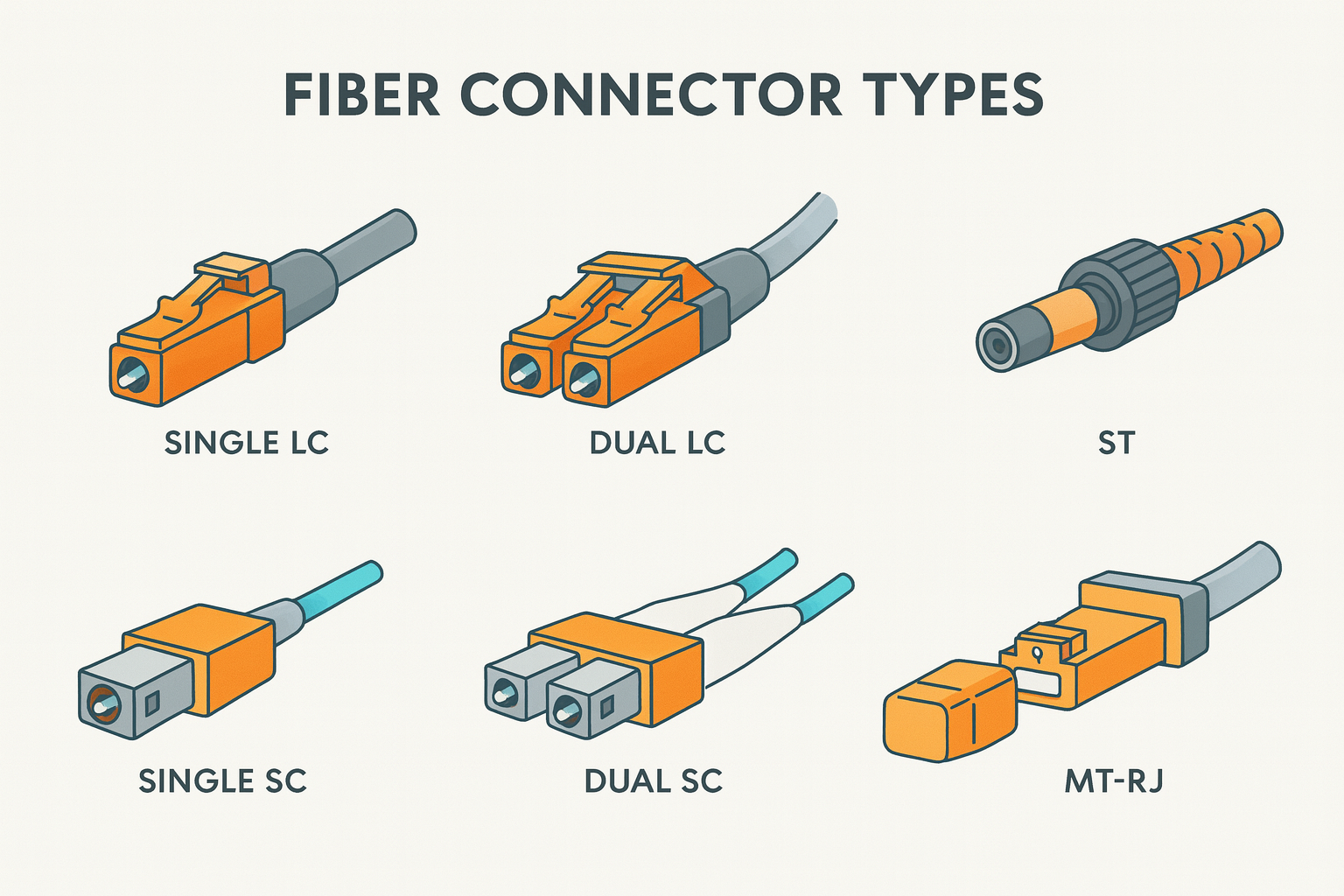
- LC (Lucent Connector): Small and common. Think “Little Connector.”
- SC (Subscriber Connector): Square-shaped, larger, and durable.
- ST (Straight Tip): Twist-lock style, older but still seen in some setups.
CCNA Exam Tip
A quick memory trick—LC = Little, SC = Square, ST = Stick and Twist.
Transceivers: The Middlemen
Your switch or router can’t just “talk light.” That’s where transceivers come in.
- SFP (Small Form-Factor Pluggable): Supports up to 1 Gbps.
- SFP+: Supports up to 10 Gbps.
- QSFP: Used for even higher speeds like 40 Gbps.
Think of transceivers as SIM cards for your network devices. You pick the right one for your fiber type and speed, plug it in, and you’re ready to go.
Where You’ll See Fiber in Action
Fiber optics is everywhere—even if you don’t notice it.
- Home internet: FTTH (Fiber to the Home) services bring blazing speeds.
- Business campuses: Single-mode fiber connects buildings across a city.
- Data centers: Multimode fiber links servers, switches, and storage with insane speeds.
- Undersea cables: The internet’s true backbone. These giant bundles of fiber stretch across oceans, letting you watch cat videos in New York that are hosted on servers in Japan.
The Human Analogy: Party Talk
Think of copper and fiber as two ways of shouting across a room.
- Copper is like yelling. It works for short distances but gets distorted if the room is noisy.
- Fiber is like using a laser pointer to send signals to your friend’s eye—super precise, immune to noise, and able to travel long distances.
That’s why fiber wins every time for big networks.
What to Remember for Your CCNA Exam
Now let’s make this exam-friendly. Here are the gold nuggets to keep in mind:
- Multimode vs. Single-Mode
- MMF = short distances, LEDs, cheaper.
- SMF = long distances, lasers, expensive but powerful.
- Mnemonic: “MMF = Many lanes, Short trip. SMF = Single track, Long trip.”
- Copper vs. Fiber Limits
- Copper max distance = 100 meters.
- Fiber = tens of kilometers.
- Connectors
- LC = Little Connector (small).
- SC = Square.
- ST = Stick and Twist.
- Transceivers
- SFP = 1 Gbps.
- SFP+ = 10 Gbps.
- QSFP = 40 Gbps.
- Noise Immunity
- Copper suffers from EMI.
- Fiber is immune.
Key Takeaways
- Fiber optics is the backbone of modern networks, carrying data at the speed of light.
- Multimode = short runs, single-mode = long-haul.
- Copper is fine for desktops, but fiber rules the backbone.
- Connectors and transceivers are essential to make fiber connections work.
- For the exam: distances, connector types, and speed limits are the big things to memorize.
CCNA Exam Tips
If the question mentions long distance → answer is single-mode fiber.
If the question mentions short, cheap, inside building → answer is multimode fiber.
If you see EMI or interference → fiber is always the right choice.
Memorize the 100-meter copper limit. It shows up often.
Remember connector shapes and names—easy exam points.
With this, you’ve got not just the technical knowledge but also the mental shortcuts to ace any fiber-related CCNA question.
Fiber optics might be invisible to the naked eye, but now you can see how it truly is the light that powers the internet.
Packing Data: Inside an Ethernet Frame
Ever shipped a package? You don’t just throw your stuff in the mail—you put it in a box, slap on an address label, maybe even bubble wrap. The Ethernet frame works the same way.
Ethernet Frame Structure
When computers talk over Ethernet, they don’t just throw random bits into the wire.
They first pack the data into a container called a frame.
Think of a frame as a digital envelope:
- Inside = your actual message (the data).
- Outside = important delivery info (who it’s for, who sent it, and how to check if it arrived safely).
The most common one you’ll see in networking is the Ethernet II frame. Let’s break it down.
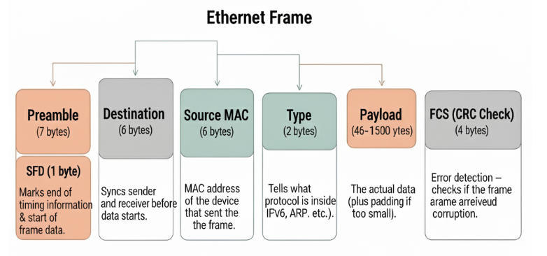
The Parts of an Ethernet Frame
| Field | Size (bytes) | Purpose | Real-life analogy |
|---|---|---|---|
| Preamble | 7 + 1 SFD = 8 | Syncs sender and receiver before data starts. | “Ready, set, go!” before a race. |
| Destination MAC | 6 | MAC address of the device that should receive the frame. | The “To:” on a letter. |
| Source MAC | 6 | MAC address of the device that sent the frame. | The “From:” on a letter. |
| Type | 2 | Tells what protocol is inside (IPv4, IPv6, ARP, etc.). | A label on a package: “Fragile,” “Electronics.” |
| Payload | 46–1500 | The actual data (plus padding if too small). | The content of the letter. |
| FCS (CRC Check) | 4 | Error detection – checks if the frame arrived without corruption. | Barcode scan when a package is delivered. |
Field-by-Field Explanation
1. Preamble (8 bytes)
- A pattern of alternating
1sand0s. - Helps devices synchronize clocks and prepare for data.
- Analogy: Like someone shouting “3, 2, 1, Go!” before the actual race begins.
2. Destination MAC Address (6 bytes)
- Tells who the frame is for.
- Only the device with that MAC address accepts it.
- Example: Your PC sends a frame to the MAC address of your printer.
3. Source MAC Address (6 bytes)
- Tells who sent the frame.
- Useful for replying back.
- Example: Your printer sees the frame came from your PC’s MAC, so it knows where to send the response.
4. Type (2 bytes)
- Identifies the protocol inside the frame:
0x0800→ IPv40x86DD→ IPv60x0806→ ARP
- Analogy: Like a package label – “Books,” “Electronics,” “Food.”
5. Payload (46–1500 bytes)
- The actual data being transmitted (like your email, video, or web page).
- If the message is too short (<46 bytes), Ethernet adds padding to reach the minimum size.
- Analogy: A small note still goes in a standard-sized envelope – filler is added so the envelope doesn’t get lost.
6. FCS (Frame Check Sequence, 4 bytes)
- Uses CRC (Cyclic Redundancy Check) to detect transmission errors.
- If the check fails, the frame is discarded.
- Analogy: A barcode scanned at delivery – if it doesn’t match, the package is marked as damaged.
Quick Recap Table
| Field | What it does | Key fact |
|---|---|---|
| Preamble | Sync signal | Always 8 bytes |
| Destination MAC | Who receives it | 6 bytes |
| Source MAC | Who sent it | 6 bytes |
| Type | Protocol inside | 2 bytes |
| Payload | Actual data + padding | 46–1500 bytes |
| FCS | Error detection | 4 bytes (CRC) |
Key Takeaways
- Frames = digital envelopes that carry data across a LAN.
- Always remember the field order:
Preamble → Destination MAC → Source MAC → Type → Payload → FCS.- Minimum frame size (without preamble) = 64 bytes.
- Maximum frame size = 1518 bytes.
- CRC detects errors, it doesn’t fix them.
CCNA Exam Tips
Memorize the field sizes (especially MAC = 6 bytes, Type = 2 bytes, FCS = 4 bytes).
Know the protocol type values: IPv4, IPv6, ARP.
Expect questions about minimum and maximum frame sizes.
Understand the difference between addressing (MAC) and protocol type (IPv4, IPv6).
MAC Addresses: The Digital Fingerprints of Networking
Every device on a network needs a unique identifier, like a digital license plate. That’s the MAC address (Media Access Control address).
- It’s 48 bits long (shown as 12 hex characters).
- It’s burned into the network card at the factory.
Think of it this way:
- IP address = your street address (can change if you move).
- MAC address = your fingerprint (unique and permanent).
Switches rely on MAC addresses to figure out who’s who inside the network.
When two devices talk to each other on a local network (like your laptop to your Wi-Fi router), they need a way to recognize each other. That’s where the MAC address comes in. Think of it like a digital fingerprint for every network card in the world.
It’s called a Media Access Control (MAC) address, and every Network Interface Card (NIC) gets one.
Examples of how you might see it:
- Cisco style (dotted):
1A2B.3C4D.5E6F - Unix/Linux style (colon):
1A:2B:3C:4D:5E:6F - Windows style (dash):
1A-2B-3C-4D-5E-6F
Same address, just different display styles.
Two Halves of a MAC
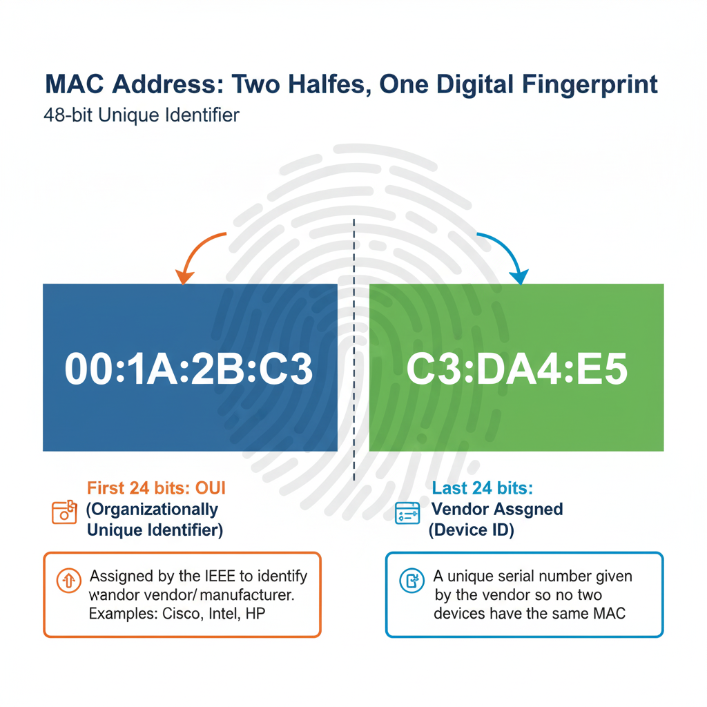
- First 24 bits → OUI (Organizationally Unique Identifier)
- This is assigned by the IEEE to identify the vendor/manufacturer.
- Example: Cisco, Intel, HP, etc. Each has their own OUI.
- Last 24 bits → Vendor Assigned (Device ID)
- This is like a unique serial number given by the vendor so no two devices end up with the same MAC.
Important Bits in a MAC Address
The first byte (8 bits) has two special little flags that make MAC addresses smarter:
- I/G (Individual/Group) Bit
- 0 = Individual (Unicast) → The address is for one device.
- 1 = Group (Multicast/Broadcast) → The address is for multiple devices.
- Sending to just your printer (unicast).
- Or blasting a “who’s online?” message to everyone on the LAN (broadcast).
- U/L (Universal/Local) Bit
- 0 = Universally Administered → The MAC was assigned by the manufacturer.
- 1 = Locally Administered → Someone changed the MAC manually. (This is sometimes done for privacy or testing.)
Why Hexadecimal?
- Decimal uses 0–9 → 10 symbols.
- Hexadecimal uses 0–9 and A–F → 16 symbols.
- Each hex digit = 4 bits.
- Since MAC addresses are 48 bits, that’s 12 hex digits.
Example:
Binary: 1010 → Hex: A
Binary: 1111 → Hex: F
So a MAC looks way cleaner in hex!
Key Takeaways
- MAC = 48-bit physical address burned into the NIC.
- Written in hexadecimal (12 digits).
- First 24 bits = OUI (vendor/manufacturer).
- Last 24 bits = Unique device ID assigned by vendor.
- Two special bits in the first byte:
- I/G bit → Unicast vs Broadcast/Multicast.
- U/L bit → Universal vs Locally assigned.
- Formats:
xx:xx:xx:xx:xx:xx,xx-xx-xx-xx-xx-xx,xxxx.xxxx.xxxx.
CCNA Exam Tips
Remember 48 bits = 6 bytes = 12 hex digits.
OUI is vendor-assigned, last 24 bits are unique per device.
I/G = 0 (Unicast), I/G = 1 (Multicast/Broadcast).
U/L = 0 (Global/Universal), U/L = 1 (Local/Modified).
Practice spotting MAC address formats. Cisco exams love to switch styles (colons, dashes, dots).
Don’t mix up IP addresses (Layer 3, logical) with MAC addresses (Layer 2, physical).
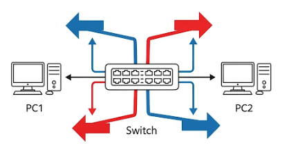
The Post Office of the Network: Frame Switching
Imagine a chaotic intersection with no traffic lights. Cars honk, people get stuck, and nothing moves smoothly. That’s what early networks were like.
Switches came to the rescue by acting like super-organized traffic managers. They:
- Learn which MAC address lives on which port.
- Build a little “map” called a MAC address table.
- Use that table to send frames only to the correct destination.
Instead of blasting traffic everywhere, switches make sure only the right “car” enters the right “street.” This reduces chaos and keeps the network efficient.
Setting the Stage
When you connect devices on a network, they need to send data back and forth. But imagine 50 devices all plugged into one switch — how does the switch know where to send each frame? That’s where frame switching comes in.
Think of it like a super-fast post office inside your network: every frame (little package of data) comes in, the switch checks the “address label” (the MAC address), and then decides which “mailbox” (port) to send it to.
What is a Frame?
A frame is simply a chunk of data at Layer 2 (Data Link layer).
It’s like an envelope carrying your message across the local network. Inside the envelope:
- Source MAC address (who sent it)
- Destination MAC address (who should get it)
- Payload (the actual data, like your cat video or Zoom call)
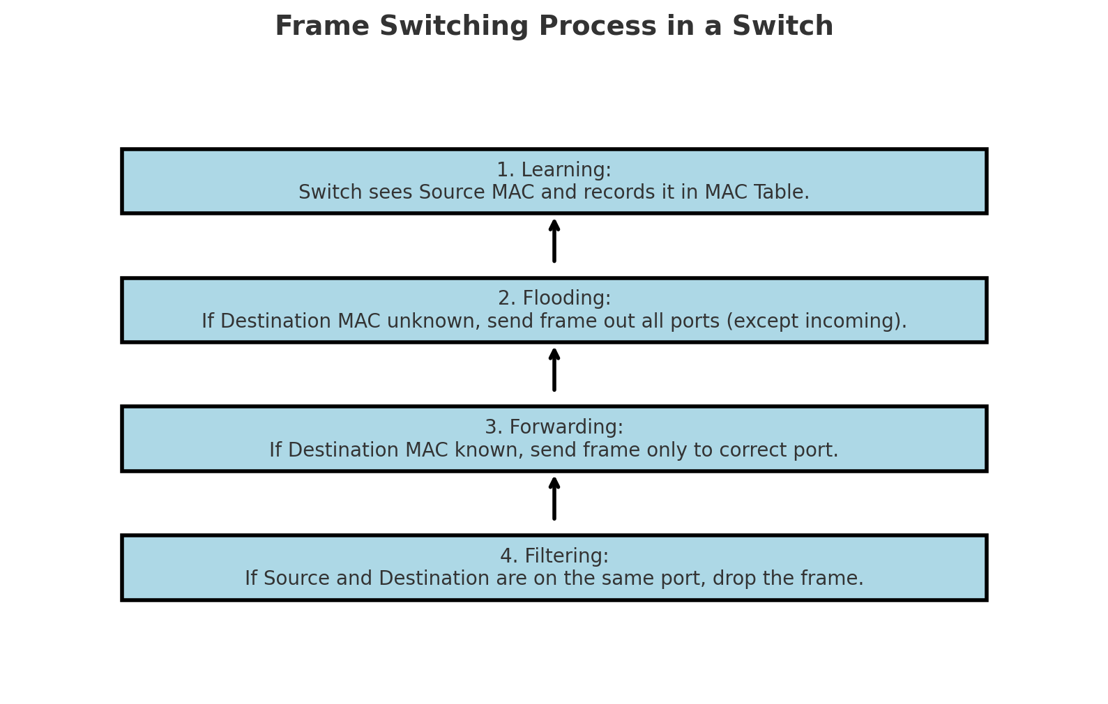
How Frame Switching Works
When a frame enters a switch, four main steps happen:
- Learning
- The switch looks at the source MAC address and records which port it came from.
- Example: It learns “PC1 with MAC
AA-BB-CC-11-22-33is on Port 1.”
- Forwarding / Switching
- The switch checks the destination MAC address.
- If it knows the port for that MAC, it sends the frame directly there.
- Flooding
- If the switch doesn’t know the destination MAC yet, it sends the frame out of all ports (except the one it came from).
- Kind of like yelling, “Hey, who owns this MAC?”
- Once the right device replies, the switch learns where it lives.
- Filtering
- If the frame’s destination MAC is on the same port it came in, the switch drops it. No need to send it back to the same device.
Switch Forwarding Methods
Switches don’t all behave the same. They can use different strategies to decide when to forward frames:
- Store-and-Forward
- The switch receives the entire frame, checks for errors (CRC), then forwards it.
- Very reliable but adds a tiny bit of delay.
- Cut-Through
- The switch starts forwarding as soon as it reads the destination MAC (first 6 bytes).
- Super fast but errors might slip through.
- Fragment-Free
- A middle ground: the switch waits long enough to avoid most errors (first 64 bytes), then forwards.
- A balance between speed and reliability.
Switching Table (MAC Address Table)
Inside the switch lives a MAC Address Table (or CAM table).
This is the “phone book” the switch uses to match MAC addresses to ports.
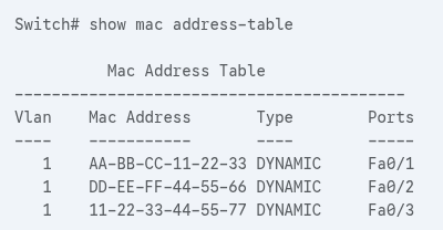
Without this table, the switch would be yelling (flooding) all the time — which isn’t efficient.
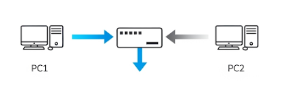
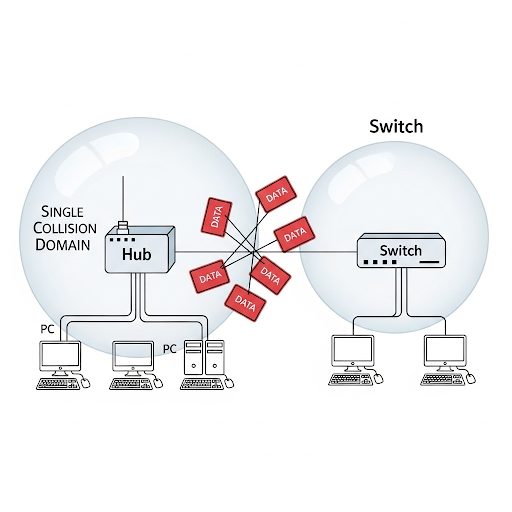
Frame Switching vs. Hub Behavior
To really appreciate switches, let’s compare them with old-school hubs:
- Hub = Dumb. It just repeats signals to all devices. It’s like shouting in a room, and everyone has to listen.
- Switch = Smart. It only delivers the frame to the correct device, like whispering in someone’s ear.
That’s why modern networks always use switches — they reduce collisions, improve speed, and keep data more private.
Why Frame Switching Matters
- Efficiency: Only the intended device gets the data.
- Security: Your data isn’t blasted to everyone on the network.
- Performance: No more collisions like in hub networks.
- Scalability: You can keep adding more devices without chaos.
Key Takeaways
- Frame = Layer 2 data unit with source & destination MAC.
- Switch uses a MAC Address Table to decide where to forward.
- Unknown destinations → Flood → Learn → Update table.
- Forwarding methods: Store-and-Forward, Cut-Through, Fragment-Free.
- Switches = smarter than hubs.
CCNA Exam Tips
Frame = Layer 2 (Packet = Layer 3, Segment = Layer 4, Bits = Layer 1).
Switches learn MAC addresses by looking at the source address.
Unknown MAC → Flood, then Learn.
Store-and-Forward checks errors, Cut-Through is faster.

Remember the difference:
Hub = one big collision domain.
Switch = one collision domain per port.
If you see “CAM Table” or “MAC Address Table,” they mean the same thing.
Switching in Action: Learning, Flooding, and Forwarding
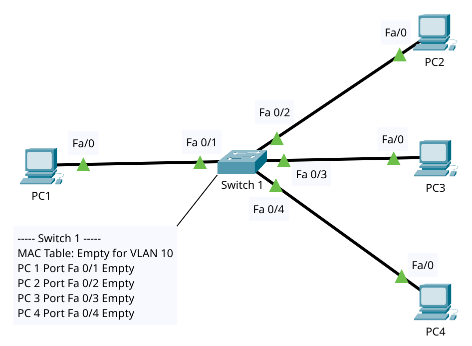
Network Topology (VLAN 10):
- PC1 (MAC
AA-BB-CC-11-22-33) on Port 1 of the switch - PC2 (MAC
DD-EE-FF-44-55-66) on Port 3 of the switch - Both in the same VLAN (VLAN 10)
- Switch starts with an empty MAC Address Table (CAM) for VLAN 10
Important: The MAC Address Table is kept per VLAN. The same MAC could appear once in VLAN 10 and again in VLAN 20 on different ports without conflict.
0) Before Any Frame Flies
- Ports: In Forwarding state (STP has already converged).
- MAC Table: Empty for VLAN 10.
- Golden Rule: A switch learns by checking the source MAC address of frames that enter a port. It does not learn from the destination field.
1) Ethernet Frame Structure Refresher
When PC1 sends a frame, the switch sees fields in this order:
- Destination MAC (6 bytes)
- Source MAC (6 bytes)
- EtherType/Length (2 bytes)
- Payload (46–1500 bytes)
- FCS/CRC (4 bytes)
Depending on the forwarding method:
- Store-and-Forward: Reads the whole frame, checks FCS; if error → drops, no learning.
- Cut-Through: Starts forwarding after reading the destination MAC; faster but errors can sneak through.
- Fragment-Free: Waits for the first 64 bytes to avoid late collisions, then forwards.
For CCNA, remember that most modern switches use Store-and-Forward.
2) How Does PC1 Even Know PC2’s MAC?
In reality, if PC1 knows PC2’s IP address but not its MAC, it uses ARP (Address Resolution Protocol).
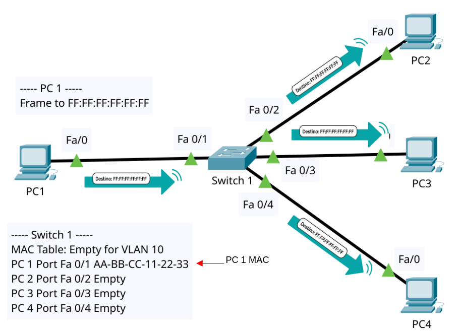
a) ARP Request (Broadcast)
- PC1 builds a frame to FF:FF:FF:FF:FF:FF (broadcast).
- When it enters Port Fa 0/1:
- Switch learns: “
AA-BB-CC-11-22-33lives on Port Fa 0/1, VLAN 10.” - Destination = broadcast ⇒ switch does not check the table; it floods the frame out all forwarding ports in VLAN 10 except Port Fa 0/1.
- Switch learns: “
- PC2 (Port Fa 0/2) receives the ARP Request and processes it.
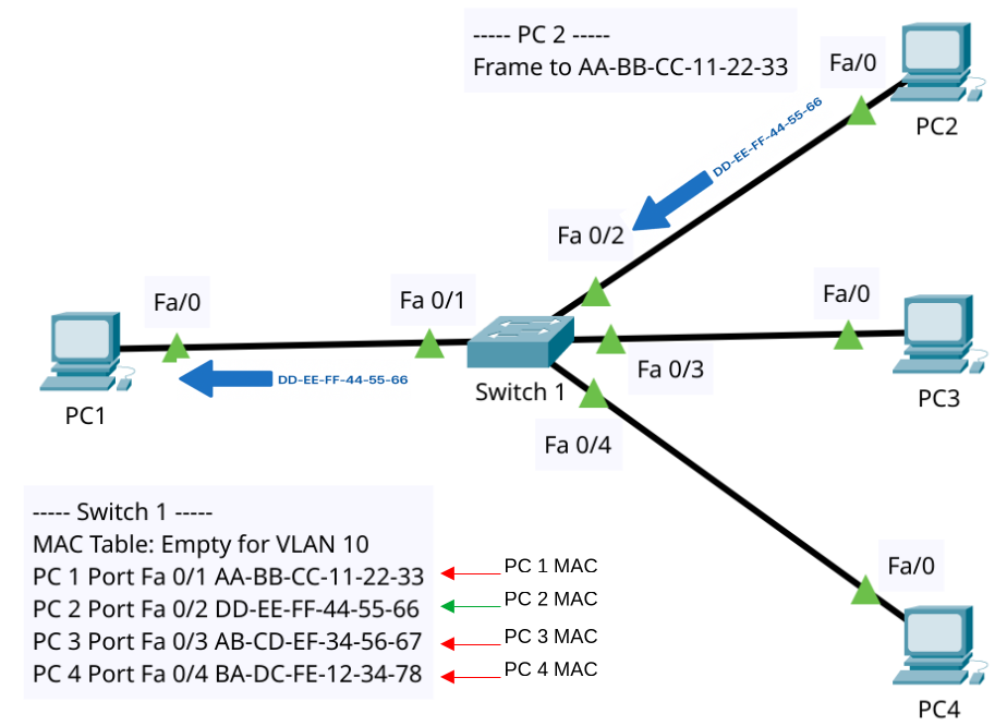
b) ARP Reply (Unicast)
- PC2 replies with a unicast frame to
AA-BB-CC-11-22-33(while PC3 and PC4 similarly send their own respective MAC addresses) - When it enters Port Fa 0/2:
- Switch learns: “
DD-EE-FF-44-55-66lives on Port Fa 0/2, VLAN 10.” - Destination =
AA-BB-CC-11-22-33⇒ found in MAC table on Port Fa 0/1. - Frame is forwarded only out Port Fa 0/1.
- Switch learns: “
Result: The switch’s MAC Table for VLAN 10 now has:
AA-BB-CC-11-22-33 → Port Fa 0/1DD-EE-FF-44-55-66 → Port Fa 0/2
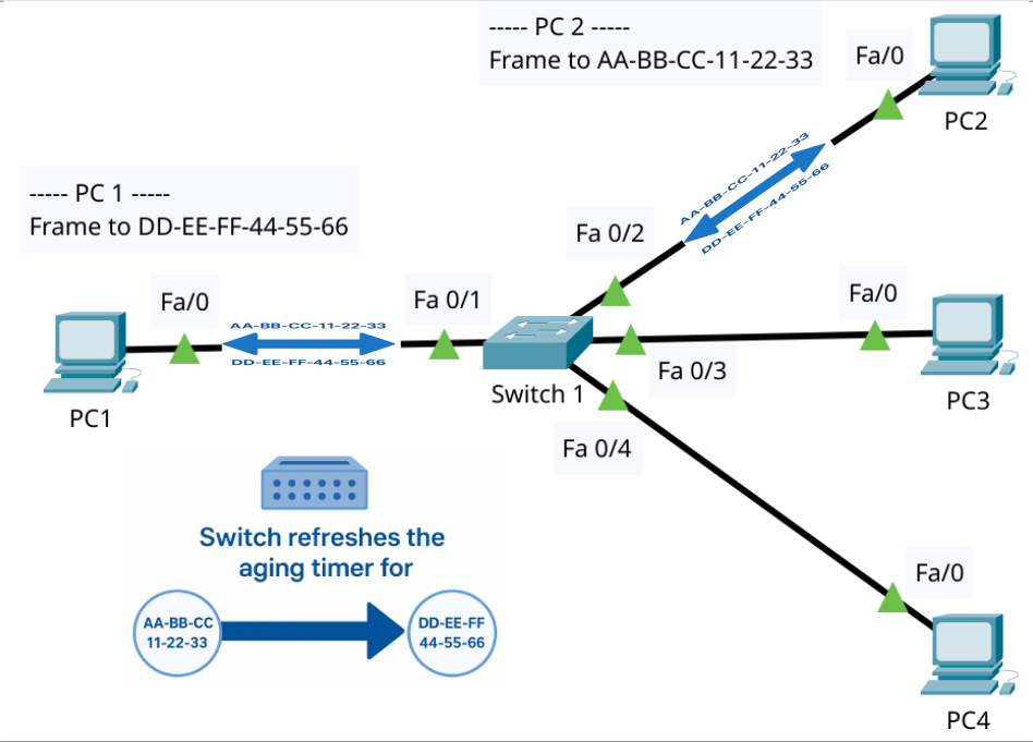
3) Data Traffic: From Shouting to Whispering
Now the MAC table is populated:
- PC1 → PC2 (unicast)
- Frame enters Port Fa 0/1.
- Switch refreshes the aging timer for
AA-BB-CC-11-22-33. - Looks up destination
DD-EE-FF-44-55-66⇒ Port Fa 0/2. - Forwards frame only out Port Fa 0/2.
- PC2 → PC1 (unicast)
- Same logic in reverse: learned source refreshed, destination matched, sent only to Port Fa 0/1.
No more flooding. The switch is now whispering frames directly to the right port.
4) MAC Aging and Table Maintenance
- Entries don’t stay forever. Typical aging timer = 300 seconds (5 minutes).
- If no frames are seen from a MAC before the timer expires, the entry is removed.
- Next time traffic arrives for that MAC, the switch may have to flood again until it relearns.
Why This Matters?
This cycle of Learning → Flooding → Forwarding → Aging is the “secret sauce” that makes switches efficient and smarter than old hubs.
- Hub: Always floods → one giant collision domain → noisy and inefficient.
- Switch: Learns and forwards → one collision domain per port → fast, quiet, scalable.
CCNA Exam Topic
Switches learn from the source MAC.
Unknown destination = flooding.
Once known, forward only to correct port.
Broadcasts always flood to all ports in VLAN except incoming one.
Store-and-Forward = error checking, Cut-Through = faster but no FCS check.
MAC aging timer = ~300 seconds (default).
This process is called Learning, Flooding, and Forwarding, and it’s the secret sauce that makes switches smarter than old hubs.
Half and Full Duplex: The Rules of Network Conversations
Remember walkie-talkies? You say “over,” then the other person replies. That’s half-duplex—one direction at a time.
Now think of a phone call. You and your friend can both talk at once (though hopefully not too much). That’s full-duplex—both directions simultaneously.
Modern Ethernet and switches run in full-duplex, meaning faster, smoother, no more awkward “you go first, no you go first” moments.
Talking Without Talking Over Each Other
Imagine you and your best friend are on a phone call. If you both talk at the same time, it becomes chaos. But if you take turns, the conversation makes sense. This everyday situation is basically what “duplex” means in networking—it’s about how data talks back and forth across a connection.
In networking, devices like PCs, switches, and routers need to communicate in ways that avoid messy collisions. That’s where half duplex and full duplex step in. These two modes decide whether communication is like a walkie-talkie (one at a time) or a phone call (both at once).
What is Duplex in Networking?
“Duplex” simply refers to how data flows between two devices. There are three main flavors:
- Simplex – One-way only (like a TV broadcast).
- Half Duplex – Two-way, but only one at a time (like a walkie-talkie).
- Full Duplex – Two-way at the same time (like a phone call).
In CCNA world, the most relevant ones are half and full duplex, so let’s zoom in there.
Half Duplex: The Walkie-Talkie Style
Half duplex allows data to flow in both directions, but not simultaneously. One device must wait until the other is finished before replying.
- Analogy: Imagine two people using a walkie-talkie. One presses the button to speak while the other waits. “Over!” signals it’s the next person’s turn.
- Networking Reality: Early Ethernet hubs and coaxial cable networks used half duplex. They had to deal with collisions, which happen when two devices try talking at the same time.
- How It Works: The devices follow Carrier Sense Multiple Access with Collision Detection (CSMA/CD). They “listen” before speaking. If two “speak” at once, both stop, wait a random time, and try again.
- Drawback: Collisions = delays. The busier the network, the worse it gets.
Example in CCNA:
- Old-school Ethernet hubs.
- Wireless networks often mimic half duplex because only one device transmits on a channel at a time.
Full Duplex: The Phone Call Style
Full duplex allows simultaneous two-way communication. Both devices can send and receive data at the same time without waiting.
- Analogy: Just like on a phone call—you can talk and listen simultaneously.
- Networking Reality: Modern Ethernet with switches runs on full duplex. Switches give each device its own collision-free path. No more CSMA/CD headaches.
- Benefit: Doubles the efficiency of the link. A 100 Mbps connection in full duplex can handle 100 Mbps sending + 100 Mbps receiving = effectively 200 Mbps of throughput.
- Requirement: Both ends (e.g., PC NIC and switch port) must agree on full duplex.
Example in CCNA:
- Switch to PC connections.
- Switch to Router connections.
Comparing Half vs Full Duplex
| Feature | Half Duplex | Full Duplex |
|---|---|---|
| Direction | Two-way, but one at a time | Two-way, simultaneous |
| Collisions | Yes, must detect & handle | No collisions |
| Efficiency | Lower, especially in busy networks | Higher, doubles throughput |
| Used In | Legacy hubs, some wireless | Modern switches, Ethernet links |
Think of it like traffic:
- Half duplex is a one-lane bridge with traffic lights—cars wait their turn.
- Full duplex is a two-lane highway—cars flow in both directions at once.
Duplex Mismatches: A Real-World Headache
Sometimes, one device is set to half duplex while the other is on full duplex. This is called a duplex mismatch, and it causes:
- Collisions on one end.
- Late collisions, CRC errors, and poor performance.
- The network feels sluggish even if the cable is fine.
Best Practice:
- Always configure both ends the same way (both auto-negotiation ON, or both manually set).
- On Cisco gear, auto-negotiation usually works best.
Why This Matters for CCNA
Cisco exams (and real life!) love to test your understanding of duplex. If a switchport shows lots of collisions, late collisions, or input errors, one of the first suspects is a duplex mismatch.
Real-World Analogy Recap
- Half Duplex = Walkie-Talkie. One at a time, or else it’s a mess.
- Full Duplex = Phone Call. Smooth, both talk and listen at once.
- Mismatch = One person with a walkie-talkie, the other with a phone. They’ll never get along properly.
Why Duplex Still Matters
Even though modern networks mostly run on full duplex, understanding half duplex is key to troubleshooting older devices, wireless systems, and exam scenarios. Duplex modes teach us a basic rule of networking: coordination is everything.
Without it, even the fastest link can feel like rush-hour traffic on a one-lane road.
CCNA Exam Tips
Know the definitions: Half = one at a time, Full = both at once.
CSMA/CD is only relevant in half duplex. Full duplex has no collisions, so no CSMA/CD.
Auto-negotiation usually sets speed and duplex correctly, but mismatches can happen.
Check interface errors: Late collisions = duplex problem.
Throughput math: Remember that full duplex doubles the effective bandwidth.
Key Takeaways
- Duplex = how communication flows.
- Half duplex = collisions + delays.
- Full duplex = smooth, collision-free, faster.
- Duplex mismatch = common troubleshooting issue.
- For CCNA: always be ready to identify where and why duplex matters.
The Link Layer: The Foundation That Keeps Networks Moving
The Link Layer may not be glamorous, but it’s the foundation of everything else. Without it, no fancy IP routing, no browsing, no Netflix, no cat videos. It’s where networking begins:
- Devices know how to talk (unicast, broadcast, multicast).
- Data travels through copper, fiber, or wireless.
- Frames wrap data neatly for delivery.
- MAC addresses identify each device uniquely.
- Switches direct traffic intelligently.
- Full-duplex makes conversations lightning-fast.
Master these basics, and you’ll have a rock-solid starting point for your CCNA journey.
CCNA Exam Tips
Frames: Know the fields (Source MAC, Destination MAC, Type, Data, FCS).
MAC addresses: 48 bits, written in hex, unique to each device.
Switch behavior: Learn, forward, flood when unknown.
Communication types: Unicast = one-to-one, Broadcast = one-to-all, Multicast = one-to-many.
Duplex modes: Half = one at a time, Full = both directions at once.
Media: Copper for short distances, Fiber for long/fast, Wireless for flexibility.
Key Takeaway
One thing to remember: The Link Layer is like the roads of a city. It decides how cars (data) leave your house (device), which streets they take, and how they reach your neighbor’s house. Without roads, the city can’t function — and without the Link Layer, the rest of the network can’t work.
Summary
What Did You Learn Today?
Let’s Find Out!
Instructions
- Select the correct answer for each technology concept.
- All questions pertain directly to the networking technologies explained.
- After answering, click “See Result” to see your score and feedback.
[Return to CCNA Study Hub] — Next Stop: [Section 2 | Ignite the switch]