
What You Just Saw in Network Diagram Form | Part One
A Guide to Understanding Network Diagrams, MDFs, and IDFs (Without Needing a Brain Transplant)
First Listen: let your ears lead the way before your mind takes notes.
📻 FZ2CCNA Radio:
Then read: let your eyes explore before your mind starts to explain.
Let’s Start with a Brain Metaphor (Because Why Not?)
Imagine a network as a human body. You have a brain (the core intelligence), a spine (the backbone), nerves (cables), and organs (devices like PCs, printers, routers). If your body has a communication system to keep everything coordinated, so does your network.
And guess what? Network diagrams are like x-rays of this body — they show you what’s connected where, how data flows, and where you’d stick the metaphorical thermometer when things go wrong.
What Is a Network Diagram, Really?
A network diagram is a visual map of how devices (computers, switches, routers, etc.) connect in a network. It’s like drawing the blueprint for a smart house — except instead of wires and pipes, you’ve got Ethernet links, IP addresses, and access points.
There are two main kinds:
- Physical Diagrams: Show you the actual stuff: cables, ports, hardware, closets.
- Logical Diagrams: Show you how things talk to each other logically — think data flow, IP addresses, subnets, protocols.
Meet the MDF and the IDF: Network Real Estate
MDF – Main Distribution Frame
Think of the MDF as the main electrical panel in a building. It’s where everything begins and gets distributed to the rest of the structure.
MDF = HQ (Headquarters)
It’s the first stop for all internet connections from your ISP. From there, cables (usually fiber or Ethernet) shoot out to other locations inside your building.
- Typically located in a secure IT room.
- Connects to all IDFs.
- Hosts the main routers, firewalls, and core switches.
- Your Wi-Fi gear (WAPs) can also live here.
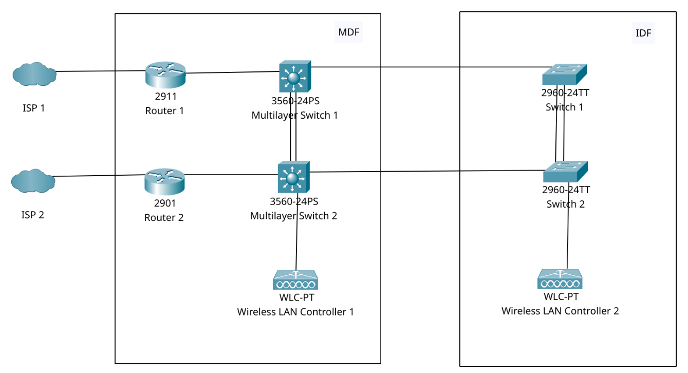
- Two ISPs → Two Routers → Core Switches → Boom! That’s the MDF.
- It’s the first box where data from outside the building gets filtered, sorted, and routed like Amazon Prime packages.
IDF – Intermediate Distribution Frame
Now picture the IDF as the mini power box on each floor of a tall building. It doesn’t get internet from the outside, but it gets a cable from the MDF and then connects locally to nearby devices.
IDF = Local Branch Office
You’ll usually find these on different floors or wings of large buildings.
- Receives the signal from the MDF.
- Has switches that serve local PCs, printers, WAPs.
- Saves cable costs (you don’t run every wire to the MDF).
MDF sends two Ethernet cables to the IDF. The IDF has two switches and a WAP (Wireless Access Point) — these provide local wired and wireless access.
Physical vs Logical Diagrams: The Great Divide
Physical Diagrams
- Show where the actual cables and devices are.
- Includes: device icons, interface names like Fa0/1, Gi0/1, or S0/0/0.
- Helps you know what is plugged into what, and where it is physically located.
Logical Diagrams
- Show how devices communicate.
- Might include IP addresses like 192.168.1.1, or subnet info like /24.
- Includes network grouping (like VLANs or subnets).
- Great for troubleshooting data flow or protocol configs (like OSPF or RIP).
Easy Analogy:
| Real World | Network Equivalent |
|---|---|
| Floor Plan of House | Physical Diagram |
| Where conversations happen | Logical Diagram |
Interface Labels: Your Network’s Street Addresses
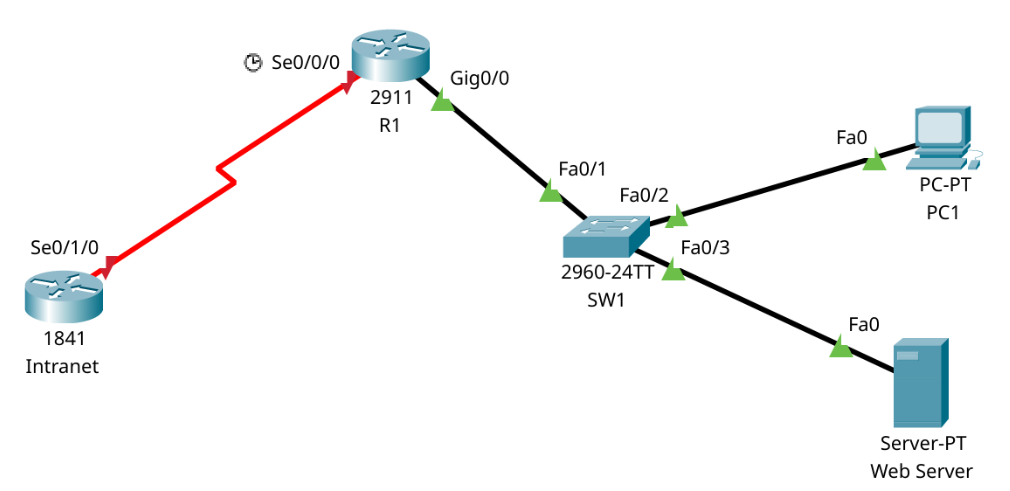
In Cisco diagrams, you’ll often see labels like Fa0/1, Gi0/0, or S0/1/0.
Here’s the cheat code:
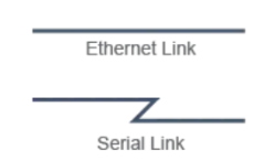
- Fa = Fast Ethernet (100 Mbps) – Ethernet Link
- Gi = Gigabit Ethernet (1000 Mbps) – Ethernet Link
- S = Serial (often WAN connections) – Serial Link
S0/0/0 means:
- Module 0
- Slot 0
- Interface 0
It’s like saying: “Hey, this is apartment 0, on floor 0, in building 0.”
This helps you know exactly where to plug in your Serial or Ethernet cable.
IP Addresses: The Home Addresses of Your Devices
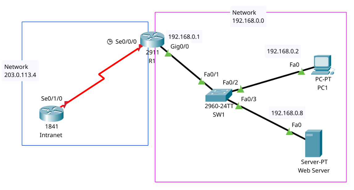
You might see something like 192.168.1.0 in a diagram.
That means:
- 192.168.0.0 is the network address.
It’s like:
- Your neighborhood is 192.168.0.0
- You live (PC) at 192.168.0.2
- Your neighbor (web Server) is 192.168.0.8
- The post office (router) is 192.168.0.1
Best Practices from the Networking Industry
- Label everything – Cables, ports, IPs. If it moves data, label it.
- Color-code cables – Use different colors for uplinks, power, fiber, etc.
- Use MDF/IDF in large buildings to avoid cable spaghetti.
- Always map both: logical AND physical diagrams. They help different teams: engineers, installers, and troubleshooters.
- Plan for growth – Leave room in the MDF and IDF for more devices.
- Use standard icons – Use Cisco symbols or clear visual icons everyone can understand.
Tips for the CCNA Exam
- You’ll be asked to identify device roles from diagrams (router, switch, etc.).
- Know your interface labels: Gi0/1, S0/0/0, etc.
- Understand the difference between logical and physical diagrams.
- Practice identifying MDF vs IDF in a setup.
- Familiarize yourself with Cisco icons: router, switch, WAP, etc.
What to Memorize
- MDF = Main Distribution Frame = Central Hub
- IDF = Intermediate Distribution Frame = Local Floor Connection
- Physical Diagram = What is connected where (cables, ports)
- Logical Diagram = How data flows and talks (IPs, protocols)
- Interface Labels:
- Fa = Fast Ethernet (100 Mbps)
- Gi = Gigabit Ethernet (1000 Mbps)
- S = Serial (for WAN links)
IP Address Format:
- 192.168.1.0
Final Takeaway
Network diagrams are your visual cheat sheet to understanding what’s going on in the tangled jungle of cables and blinking lights. Whether you’re troubleshooting a Wi-Fi issue, installing a new floor switch, or passing your CCNA, being diagram-savvy makes you 10x more valuable in IT.
What Did You Learn Today?
Let’s Find Out!
Instructions
- Select the correct answer for each technology concept.
- All questions pertain directly to the networking technologies explained.
- After answering, click “See Result” to see your score and feedback.
Next Stop: [Section 1 | Visualizing Cisco Networks]