
Mastering switch diagnostics means solving problems in minutes instead of hours.
Switch diagnostics are the X-ray vision of networking—see inside without opening it.
First Listen: let your ears lead the way before your mind takes notes.
📻 FZ2CCNA Radio:
Then read: let your eyes explore before your mind starts to explain.
Part One: Switch LED Indicators
When you look at the front of a Cisco switch, you’ll see small lights called LED indicators. These are not just decorations—they are the fastest way to understand what is happening with the switch and its ports. Each light can tell you if the system is healthy, if the power is working, and how each port is performing.
Think of them like the dashboard lights in your car. Green is usually good, amber is usually bad, and off means nothing is happening. But the meaning can change depending on which mode you are in. Let’s break it down.
System Status Light
This light shows the overall health of the switch.
- 🟢 Solid Green: The system is working normally.
- 🟠 Solid Amber (orange): There is a problem with the switch (hardware, software, or boot failure).
- ⚫ Off: The switch is not powered on.
Redundant Power Supply Light
This light shows the status of the backup power supply.
- 🟢 Solid Green: The backup power supply is connected and ready.
 Blinking Green: The backup power supply is currently in use (the main power failed).
- 🟠 Solid Amber: There is a problem with the backup power supply or it is in standby.
- ⚫ Off: No backup power supply is connected.
Power over Ethernet Light
Some switches can send power through the network cable. This is called Power over Ethernet (used for phones, cameras, and access points).
- 🟢 Solid Green: The port is providing power.
- 🟠 Solid Amber: The port tried to provide power but failed (too much power requested, or not enough power available).
- ⚫ Off: No power is being delivered.
The Mode Button
On the front of the switch, there is a Mode button. This button changes what the port lights mean. When you press the button, the lights go through different modes:
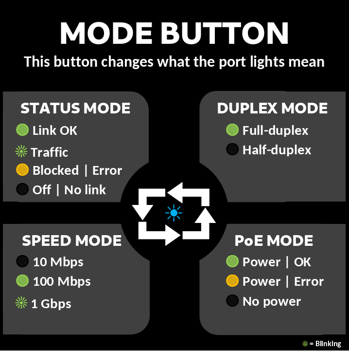
- Status Mode: Each port light shows the link and traffic status.
- Duplex Mode: Each port light shows if the port is half-duplex or full-duplex.
- Speed Mode: Each port light shows the connection speed (10 Mbps, 100 Mbps, 1 Gbps).
- Power over Ethernet Mode: Each port light shows if the port is providing power.
Port Lights
Each port has its own light, but the meaning changes depending on the mode selected with the Mode button.
In Status Mode:
- 🟢 Solid Green: A good connection is established.
- Blinking Green: Data is moving through the port.
- 🟠 Solid Amber: The port is blocked (for example, by Spanning Tree Protocol) or there is a problem.
- ⚫ Off: No device is connected or the port is disabled.
In Duplex Mode:
- 🟢 Solid Green: Full-duplex (the device can send and receive at the same time).
- ⚫ Off: Half-duplex (the device can only send or receive, but not both at the same time).
In Speed Mode:
- ⚫ Off: The port is operating at 10 Mbps.
- 🟢 Solid Green: The port is operating at 100 Mbps.
- Blinking Green: The port is operating at 1 Gbps.
In Power over Ethernet Mode:
- 🟢 Solid Green: The port is delivering power to the device.
- 🟠 Solid Amber: There is a power problem.
- ⚫ Off: No power is being delivered.
Quick Troubleshooting with LED Indicators
- If the system status light is amber, the switch has a problem.
- If all port lights are amber, the switch may be in the startup process, blocked by configuration, or have spanning tree blocking ports.
- If a port light is off in status mode, check the cable, the device on the other end, or the VLAN configuration.
- If the power over Ethernet light is green but the port light is amber, the switch tried to give power but could not.
CCNA Exam Tips
System Status: Green = good, Amber = problem, Off = no power.
Redundant Power Supply: Green = ready, Blinking Green = in use, Amber = fault, Off = not connected.
Mode Button: Changes the meaning of port lights (Status, Duplex, Speed, Power).
Port Lights in Status Mode: Green = working, Blinking Green = traffic, Amber = blocked/error, Off = no link.
Port Lights in Speed Mode: Off = 10 Mbps, Green = 100 Mbps, Blinking Green = 1 Gbps.
Power over Ethernet Mode: Green = delivering power, Amber = problem, Off = no power
Cisco may ask something like:
A port light is blinking green while the switch is in Speed Mode. What does this mean?
Answer: The port is operating at 1 Gbps.
Switch LED indicators are like free tools built into the switch. Learn to “read the lights” and you’ll save time both in real life and during your CCNA exam.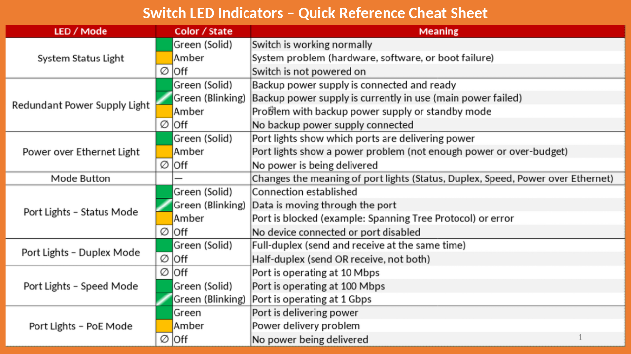
Part Two: From Zero to Troubleshooter | Cisco Show Commands
If you’ve ever worked with Cisco devices like routers or switches, you know the command-line interface (CLI) is your best friend. And at the heart of this friendship is the magic word: show.
The show command doesn’t fix anything, but it tells you exactly what’s going on inside your switch or router. With it, you can peek at configurations, check status, troubleshoot problems, and confirm whether your network is alive and well—or on fire.
This guide will walk you through the most important show commands for beginners, explain them in simple language, and give you real-world examples. Let’s get started.
Why the show Command Matters
Imagine you’re a doctor. A patient comes in and says, “I don’t feel good.” What’s the first thing you do? You check their pulse, temperature, maybe run some tests. In networking, the show command is your stethoscope.
Without it, you’re guessing in the dark. With it, you can:
- See how your device is running.
- Check if interfaces are working.
- Verify IP addresses and VLANs.
- Confirm configurations.
- Spot errors before users start yelling.
The Basics: How to Use show
The syntax is simple:
Switch> show ...something
Router# show ...something
The something part depends on what you want to see. For example:
show version→ shows software and hardware details.show running-config→ shows the current active configuration.show ip interface brief→ shows a quick summary of interfaces.
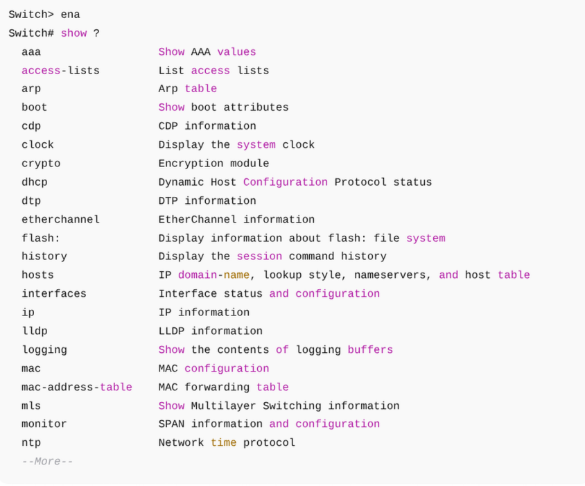
If you don’t know the exact command, type "show ?” and the device will give you a list of possible options. It’s like Google autocomplete but for networking.
Popular show Commands You Must Know
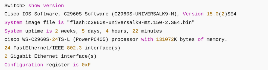
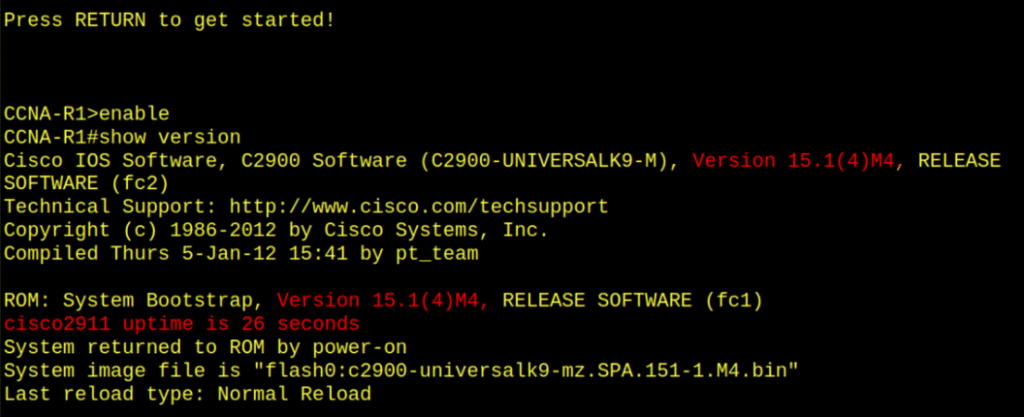
show version
This is like the ID card of your device. It tells you:
- The Cisco IOS software version.
- Device uptime (how long it’s been running).
- Model number and serial number.
- Amount of memory.
- Where the configuration file is stored.
Why it’s useful: If you ever call Cisco support, they’ll ask for this info first thing.
show running-config
Think of this as the live blueprint of your device. It shows the configuration that’s currently active in RAM.
Example:
- Hostname of the device.
- Passwords (encrypted or not).
- IP addresses on interfaces.
- VLAN and routing configurations.
Important: If you reboot the device, this config disappears unless you save it with copy running-config startup-config.
show startup-config
This is the saved configuration stored in NVRAM. It’s what the device loads when it powers on.
If you see something working in the running-config but not in the startup-config, it means you forgot to save. (Oops. Yes, this happens a lot.)
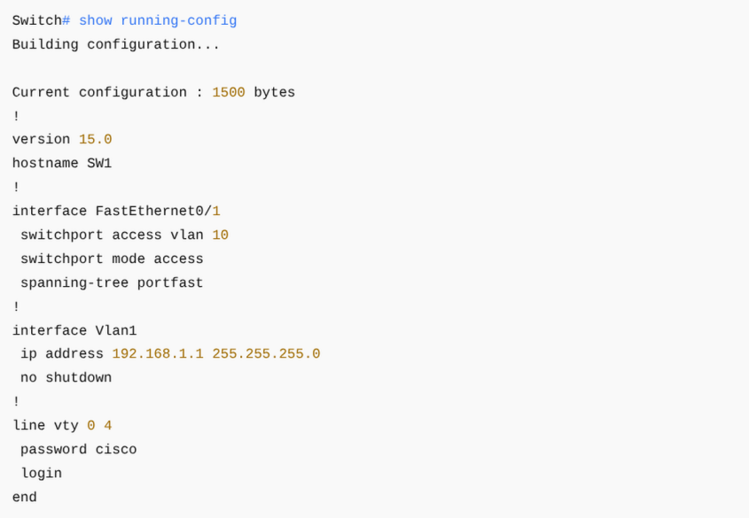
In this first image, the command executed is: show running-config
Switch# show running-configThe running-config is the configuration currently loaded in the switch’s RAM. It is the active configuration in use at that moment. In this case, you can see:
- The IOS version (15.0).
- Basic service settings.
- The hostname is still “Switch,” which means no customization has been applied yet.
This represents the initial state of a switch when it has not been configured.
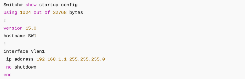
In this image, the command executed is: show startup-config
Switch# show startup-configThe startup-config is the configuration stored in NVRAM. This is the configuration the switch will load every time it reboots. Here we can see the hostname has been changed to CCNA-Switch1. This confirms two things:
- The administrator renamed the switch with:
Switch(config)# hostname CCNA-Switch1
- The change was saved to NVRAM using:
Switch# copy running-config startup-config(or the older commandwrite memory).
Saving is essential because if you only modify the running-config but don’t save it, the changes will be lost after a reboot and the hostname would revert to “Switch.”
Running-config = temporary configuration in RAM (active now).
Startup-config = permanent configuration in NVRAM (loaded at boot).
To keep changes after a reboot, always save withcopy running-config startup-config.
show ip interface brief
This one’s a lifesaver. It gives a short, easy-to-read list of all interfaces, their IP addresses, and whether they’re up or down. The output includes:
- Interface names (FastEthernet0/0, GigabitEthernet0/1, etc.).
- Assigned IP addresses.
- Status (administratively down, up, or down).
- Protocol status (whether the interface is passing traffic).
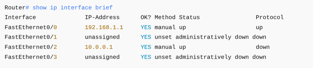
Understanding the Output of show ip interface brief
The command shown in your image is:
CCNA-Router1# show ip interface briefThis is being run on a router. We know that because:
- The hostname is CCNA-Router1, not “Switch.”
- The interfaces listed are GigabitEthernet0/0 and GigabitEthernet0/1, which are typical router ports.
- On a switch, you would normally see dozens of FastEthernet or GigabitEthernet interfaces (Fa0/1, Fa0/2, etc.), not just two.
The Output Explained
Interface              IP-Address      OK? Method Status                Protocol
GigabitEthernet0/0     192.168.1.1     YES manual up                    down
GigabitEthernet0/1     10.0.0.1        YES manual up                    down
Vlan1                  172.16.0.1      YES manual up                    down
Column by Column:
- Interface → The physical or logical interface (GigabitEthernet0/0, 0/1, Vlan1).
- IP-Address → The IP assigned to that interface. (Routers can assign IPs to physical interfaces directly. Switches can only assign an IP to a management interface, usually VLAN 1).
- OK? → Always says “YES” unless there’s a serious issue.
- Method → How the IP was assigned (manual, DHCP, etc.). Here it’s manual.
- Status → Refers to the physical layer. “up” means the interface is administratively enabled (
no shutdownhas been applied). - Protocol → Refers to the data link layer. “down” means there is no active connection (no cable, or no neighbor device on the other end).
Why This is a Router (Not a Switch)
Here’s the key distinction:
- Routers:
- You can assign IP addresses directly to their physical interfaces (Gig0/0, Gig0/1, etc.).
- This is because routers operate at Layer 3 (the network layer OIS model).
- Switches:
- You cannot assign IP addresses directly to the physical ports.
- Instead, you assign an IP address to a VLAN interface (for management purposes only).
- Example on a switch:
Switch(config)# interface vlan 1 Switch(config-if)# ip address 192.168.1.10 255.255.255.0 Switch(config-if)# no shutdownHere, the IP belongs to VLAN 1 (a virtual interface), not the actual physical port Fa0/1 or Gi0/1.
Why All Protocols are Down
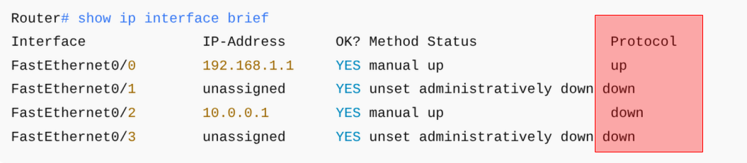
Notice how all entries show Protocol = down. This means:
- The interfaces are enabled (
Status = up) — thanks tono shutdown. - But the Protocol is still down → there’s no physical connection. Probably no cable plugged in or no device on the other side.
If you connected another router or switch to Gig0/0 and configured it correctly, you’d see both Status = up and Protocol = up.
show ip interface briefis the fastest way to check interface health.
On routers, IPs go directly on physical interfaces.
On switches, IPs go only on VLAN interfaces (for management).
Status = up but Protocol = down usually means: no cable, bad cable, or mismatch on the other end.
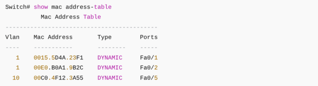
show mac address-table
This shows the MAC addresses your switch has learned and which ports they belong to.
Why important? It’s how a switch decides where to send frames. If a user says, “I can’t connect,” you can trace their MAC address to see if the switch even knows about them. Lists MAC addresses the switch has learned. The switch learned MAC 0015.5D4A.23F1 on port Fa0/1.
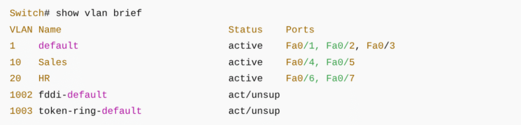
show vlan brief
VLANs are like “apartments” inside your switch. Each VLAN is a separate network.
This command shows:
- VLAN IDs.
- VLAN names.
- Which ports belong to which VLAN.
Perfect for spotting if someone plugged into the wrong network. Port Fa0/5 is in VLAN 10 (Sales).
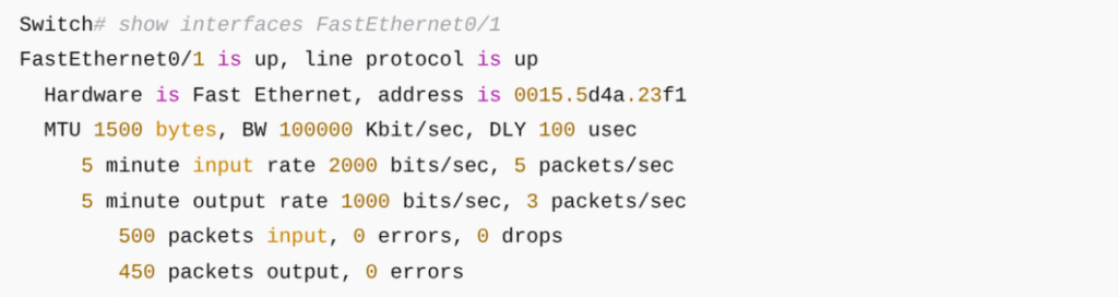
show interfaces
This is the deep-dive report for every port. It includes:
- Speed and duplex settings.
- Bandwidth utilization.
- Errors (like collisions or drops).
- Interface status.
Think of it as a car diagnostic tool: it doesn’t just say the car runs, it tells you if the tires are flat or the oil is low. You can check speed, duplex, traffic, and errors.
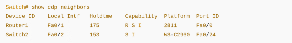
show cdp neighbors
Cisco Discovery Protocol (CDP) lets Cisco devices talk to each other.
This command shows:
- Which devices are directly connected.
- Their IPs and device IDs.
- Which port they’re connected on.
It’s like looking at your neighbors’ nameplates in an apartment hallway. You can map which devices are connected and on what ports.
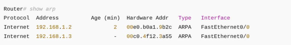
show arp
This displays the Address Resolution Protocol (ARP) table, mapping IP addresses to MAC addresses.
If you’re troubleshooting why a device can’t communicate, this table helps confirm if the device’s IP is being resolved. Confirms which IPs are associated with which MAC addresses.
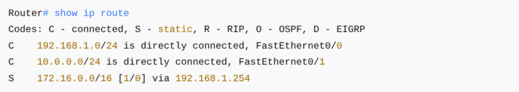
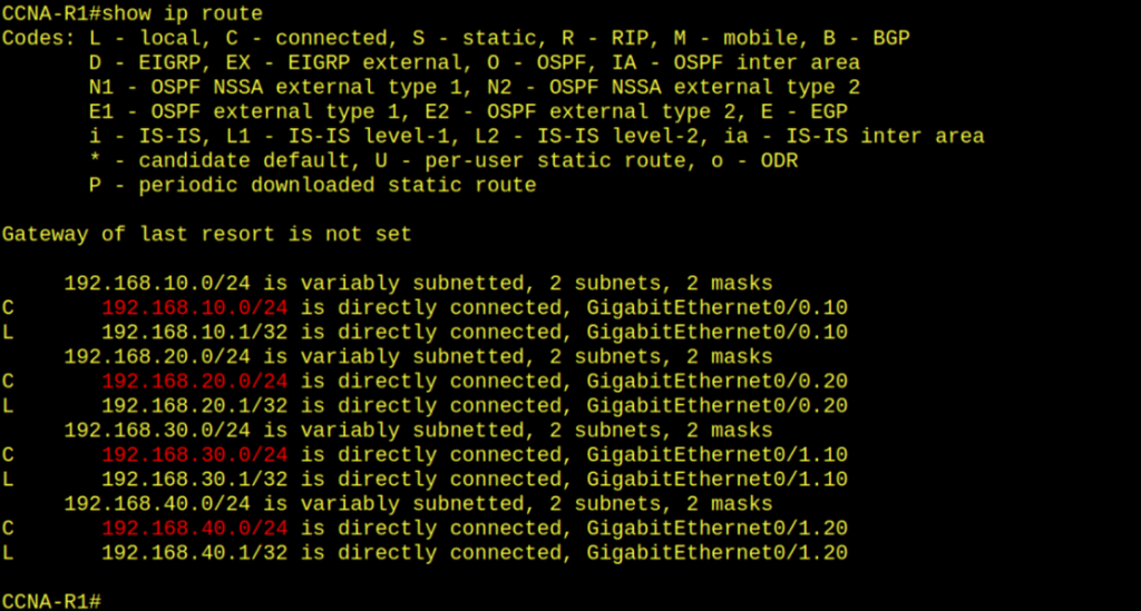
show ip route
This is your map of the network. It shows all known routes to different networks, whether they’re directly connected or learned via routing protocols.
Without this, routers wouldn’t know where to send packets.
Tips for Using show Effectively
Don’t panic with big outputs. Use| include,| begin, or| excludeto filter. Example:show running-config | include hostnameThis shows only the line with the hostname.
Take screenshots or copy outputs. They’re gold when documenting.
Practice in Packet Tracer or real labs. Reading about commands isn’t enough—you need to type them.
Real-Life Example
Imagine a user says: “I can’t get on the internet.”
Steps you might take:
show ip interface brief→ Check if the user’s interface has an IP and is up.show vlan brief→ Make sure the port is in the right VLAN.show mac address-table→ See if the switch has learned the user’s MAC.show ip route→ Confirm the router knows where to send traffic.show interfaces→ Look for errors on the port.
With just these, you’ve gone from clueless to detective mode. The show command is your gateway to understanding Cisco devices. It doesn’t change anything—it just tells you the truth. And in networking, the truth is power. Whether you’re verifying VLANs, checking interfaces, or tracing routes, mastering these commands makes you faster, smarter, and way more confident. Remember: if you ever feel lost, type show ?. The device will happily remind you of all the things it can show you.
CCNA Exam Tips
Know the difference between running-config and startup-config.show ip interface briefis the fastest way to check IPs and statuses.
Remember thatshow vlan briefonly works on switches, not routers.
On the exam, outputs might look long—scan for keywords (up/down, assigned IP, VLAN IDs).
Practice filtering (| include) so you don’t drown in text.
showcommands = visibility.running-config= now,startup-config= saved.
Interfaces have two states: administrative (set by you) and protocol (actual link).
VLANs organize ports, routes organize networks.
CDP neighbors help you map the physical topology.
Summary
What Did You Learn Today?
Let’s Find Out!
Instructions
- Select the correct answer for each technology concept.
- All questions pertain directly to the networking technologies explained.
- After answering, click “See Result” to see your score and feedback.
Lab C02T: Cisco Show Commands
Lab Goal
Learn how to use Cisco show commands on routers and switches to verify configurations, check interface health, inspect VLANs, ARP tables, and routing tables. By the end, you should be able to identify the real state of your network using only diagnostic commands.
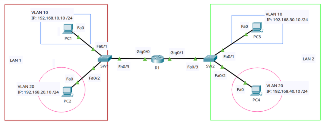
Step 1: Devices Required
- 1 Router (Cisco 2911 or similar in Packet Tracer)
- 2 Switches (2960)
- 4 PCs (to generate traffic and test connectivity)
Step 2: Topology
🛠️🖧⬇️ Download the Lab and start practicing!
- LAN 1 (left side)
- PC1 in VLAN 10 with IP 192.168.10.10/24
- PC2 in VLAN 20 with IP 192.168.20.10/24
- Both connected to SW1
- LAN 2 (right side)
- PC3 in VLAN 10 with IP 192.168.30.10/24
- PC4 in VLAN 20 with IP 192.168.40.10/24
- Both connected to SW2
- Router R1
- Connected between SW1 (Gig0/0) and SW2 (Gig0/1)
- Acts as the Layer 3 device to allow inter-VLAN routing and communication between LAN 1 and LAN 2
- Switches (SW1, SW2)
- Layer 2 devices connecting end devices in their VLANs.
The command ping 192.168.10.1 implies testing connectivity to the default gateway for VLAN 10 in LAN 1.
Practice Lab: Analyzing the Topology with Show Commands
Step 1 – Router R1
- Run:
show version- Question: What model is the router? How long has it been running?
- Run:
show running-config- Question: Which IP addresses are configured on R1’s interfaces?
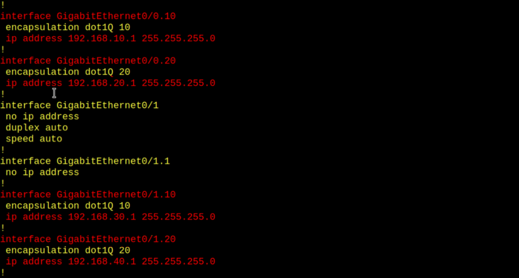
- Run:
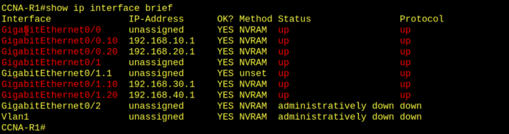
show ip interface brief- Question: Which interfaces are up/up? Do they match the diagram?
- Run:
show ip route- Question: Which networks does R1 know about? How does it learn them?
Your turn— prove to yourself you can do it.
Step 2 – Switch SW1 and SW2
- Run:
show vlan brief- Question: Do you see VLAN 10 and VLAN 20? Which ports are assigned to each VLAN?
- Run:
show mac address-table- Question: Which MAC addresses belong to PC1, PC2, PC3, and PC4? Which VLANs are they in?
- Run:
show interfaces- Question: Are there any errors or collisions on the switch ports?
- Run:
show cdp neighbors- Question: Which neighboring devices are directly connected to this switch? Does it match the topology diagram?
Step 3 – Switches
- Run:
show arp- Question: Which IP-to-MAC mappings appear in the ARP table? Can you identify each PC’s MAC address?
Step 4 – Cross-check Configuration
- Question: If you reload the device, will it keep the same configuration? What’s the difference between
running-configandstartup-config? - On both router and switches: Run
show startup-config
[Return to CCNA Study Hub] — Next Stop: [Section 2 | Initial Configuration]