
Switches and the OSI Model
Switch troubleshooting is a core CCNA skill because many network failures begin at the switch port, the cable, or the Ethernet settings on a link. A switch works across multiple OSI layers, so problems can appear as physical connectivity failures, frame forwarding issues, or management reachability problems. In this section, you will learn how to identify copper and fiber media issues, detect duplex and speed mismatches, interpret show interfaces output, and follow a practical troubleshooting process for switch connectivity problems.
Definition
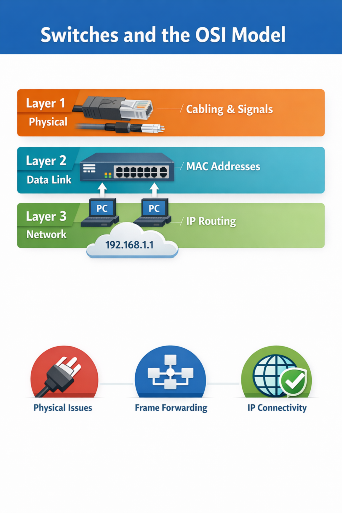
A switch is a network device that commonly operates at:
- Layer 1 (Physical layer): electrical, optical, and physical interface connection
- Layer 2 (Data Link layer): forwarding Ethernet frames using MAC addresses
- Layer 3 (Network layer): management access or multilayer switching on some platforms
A MAC address is the Layer 2 hardware address used to identify a network interface on an Ethernet network.
How It Works
- At Layer 1, the switch provides the physical port and signaling used by copper or fiber links.
- At Layer 2, the switch receives Ethernet frames and decides where to forward them based on destination MAC address.
- For management, the switch may also use Layer 3 addressing such as an IP address on a VLAN interface.
- Because of this, switch issues are often:
- Layer 1: bad cabling, connector damage, noise, bad transceiver
- Layer 2: collisions, duplex mismatch, CRC errors, forwarding issues
- Layer 3: inability to ping the switch management IP
OSI Layer(s)
- Layer 1: media, connectors, signal integrity
- Layer 2: Ethernet framing, MAC addressing, duplex
- Layer 3: IP connectivity for management access
Protocols Involved
- Ethernet: Layer 1 and Layer 2 technology used on LANs
- IP: Layer 3 protocol used for management connectivity
- ICMP: used by
pingto test Layer 3 reachability
Relevant Cisco Commands
show interfaces
Displays interface status, speed, duplex, errors, collisions, CRC, and queue statistics.ping
Tests Layer 3 IP connectivity.traceroute
Helps locate where a Layer 3 path fails.
Real-World Examples
- In an office network, a user loses connectivity because the switch port is down.
- In a campus network, a switch forwards frames normally at Layer 2, but its management IP cannot be reached at Layer 3.
- In a data center, a fiber uplink has physical signal loss while the switch logic is functioning correctly.
Basic Troubleshooting
- Check whether the issue is physical, data link, or management IP related.
- Verify:
- port LEDs
- cable condition
- interface status
- MAC learning
- IP reachability to the switch management interface
Important Points
- A switch can present problems at more than one OSI layer.
- Most switch access-port issues are Layer 1 or Layer 2.
- Management failures can also be Layer 3 issues.
- Always identify the OSI layer before making changes.
Key Idea
Switch troubleshooting starts by determining whether the failure is physical, Ethernet-related, or IP-related. Because switches operate across Layers 1, 2, and sometimes 3, accurate troubleshooting depends on checking the correct layer first.
Copper Media Issues
Definition
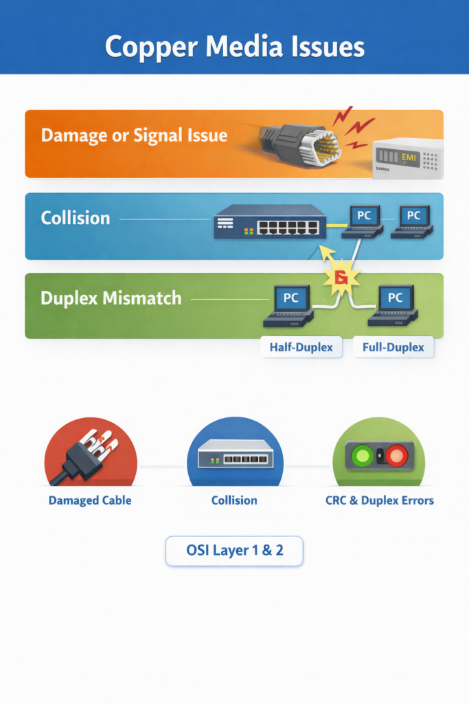
Copper media issues are physical or electrical problems affecting Ethernet communication over copper cabling such as twisted-pair cables with RJ-45 connectors. EMI (Electromagnetic Interference) is unwanted electrical noise that can disrupt signals on copper cables. CRC (Cyclic Redundancy Check) is an error-checking value used to detect corrupted Ethernet frames. Collision is an Ethernet event in which two devices transmit at the same time on a shared or half-duplex medium.
How It Works
- Copper Ethernet relies on correct cable type, good connectors, and clean electrical signaling.
- If the cable is damaged or exposed to excessive EMI, frames may arrive corrupted.
- Corrupted frames often increase interface error counters such as CRC errors.
- If traffic patterns change because new devices or hubs are introduced, collision rates may increase.
- If one side of a link uses full-duplex and the other side uses half-duplex, the link can suffer from severe performance problems and collisions.
Common copper issue sources
- Damaged wiring
- Poor cable management
- EMI from nearby equipment
- Bad RJ-45 connectors
- New devices changing traffic behavior
- Hubs causing half-duplex operation
- Speed or duplex mismatch
Category-related note
Lower cable categories are generally more vulnerable to signal problems. For Fast Ethernet, using at least Category 5 is recommended.
OSI Layer(s)
- Layer 1: cable, connector, electrical signal, EMI
- Layer 2: collisions, Ethernet frame corruption, duplex-related issues
Protocols Involved
- Ethernet: defines how frames are sent on the LAN
- CDP (Cisco Discovery Protocol): Cisco proprietary protocol that can help detect duplex mismatches between Cisco devices
Relevant Cisco Commands
show interfaces
Checks operational status, CRC errors, collisions, speed, and duplex.show interface fa0/1
Same function for a specific interface such as FastEthernet0/1.
Real-World Examples
- In an enterprise office, a cable routed near electrical equipment causes CRC errors.
- In a small branch, a user plugs a hub into a switch port, creating half-duplex behavior and increased collisions.
- In a server room, cable strain damages an RJ-45 connector, causing intermittent port flaps.
Basic Troubleshooting
- Inspect cable path and connector condition.
- Check if cable length exceeds Ethernet limits.
- Look for CRC increases with stable collision count, which suggests noise.
- Replace suspect copper patch cables first.
- Verify whether hubs or poorly behaving NICs are present.
Important Points
- Copper issues are commonly Layer 1 problems with Layer 2 symptoms.
- CRC increases without collision spikes can indicate noise.
- Hubs and half-duplex operation can increase collisions.
- Cable quality and installation practices matter.
Key Idea
Copper media problems usually begin at the physical layer but often appear as Ethernet frame errors. The most useful first checks are cable condition, interface counters, and speed/duplex consistency.
Late Collisions, CRC Errors, Jabbering, and TDR Use
Definition
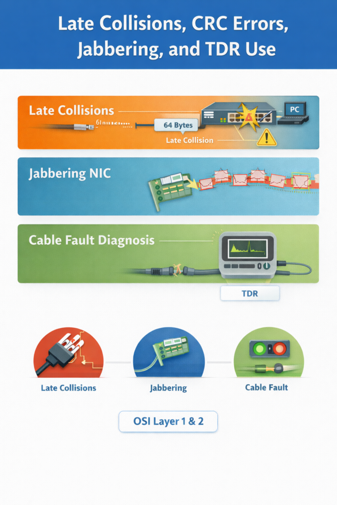
A late collision is a collision detected after the first 512 bits (64 bytes) of an Ethernet frame have been transmitted. Jabbering is a condition in which a NIC or device continuously sends invalid or excessive data onto the network. A TDR (Time-Domain Reflectometer) is a diagnostic tool used to identify cable faults such as breaks or improper termination.
How It Works
- In properly designed Ethernet, collisions should occur only within the expected timing window.
- If a collision occurs after 64 bytes, it is classified as a late collision.
- Late collisions are serious because Ethernet does not automatically retransmit them at the NIC level.
- Upper-layer protocols must recover from the lost data.
- Common causes include:
- duplex mismatch
- incorrect cabling
- excessive cable distance
- bad NIC
- noncompliant hub design
- A jabbering NIC can inject garbage traffic and increase collisions.
- A TDR can help identify cable reflection problems caused by improper termination or damaged cable sections.
OSI Layer(s)
- Layer 1: cable faults, signal reflection
- Layer 2: collisions, frame transmission behavior
Protocols Involved
- Ethernet: defines collision handling behavior
Relevant Cisco Commands
show interfaces
Used to view collision counters and interface error information.
Real-World Examples
- In a legacy office network with old hubs, excessive cable distance causes late collisions.
- In a campus lab, a defective NIC begins jabbering and floods invalid frames onto a shared segment.
Basic Troubleshooting
- Check for late collisions in interface statistics or packet analysis tools.
- Verify cabling distance and media type.
- Remove hubs where possible.
- Replace suspect NICs.
- Use a TDR-capable platform or tester to locate cable faults.
Important Points
- Late collisions should not happen in a properly designed Ethernet network.
- Duplex mismatch is one of the most common causes.
- Jabbering devices can create collision-related performance problems.
- TDR helps locate physical cable defects.
Key Idea
Late collisions indicate a serious Ethernet design or configuration problem, not normal network operation. Common causes include duplex mismatch, bad cabling, and faulty NIC hardware.
Fiber Media Issues
Definition
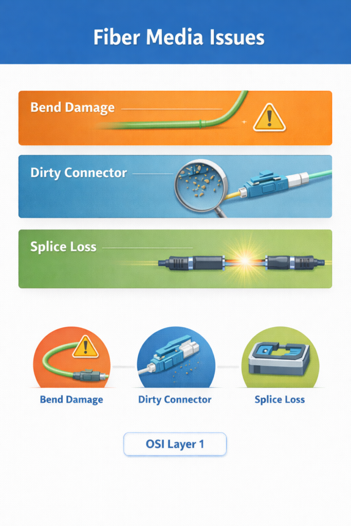
Fiber media issues are optical transmission problems that reduce or block light traveling through fiber-optic cable.
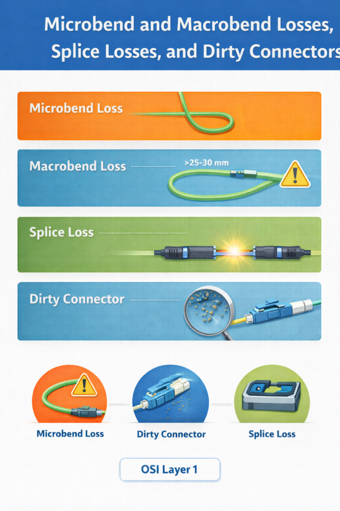
Common causes include:
- Microbend loss
- Macrobend loss
- Splice loss
- Dirty connectors
A splice is a connection between two fiber strands, usually created by fusing them.
How It Works
- Fiber sends data as light through a core surrounded by cladding.
- Light must remain inside the core through total internal reflection.
- If the fiber bends too sharply, light may escape from the core.
- If a splice is poorly aligned, part of the light does not continue into the next fiber.
- If the connector endface is dirty, dust or oil can block or reflect the signal.
- Excessive optical loss weakens the received signal and can cause link failure or unstable performance.
OSI Layer(s)
- Layer 1: optical transmission medium and physical connection
Protocols Involved
No major Layer 2 or Layer 3 protocol creates the fiber problem itself. The issue is physical transmission at Layer 1.
Relevant Cisco Commands
show interfaces
Can confirm whether the fiber interface is up and may show errors.- Platform-specific optical commands may also exist, but the core command emphasized here is
show interfaces.
Real-World Examples
- In a data center, a patch cable is bent too tightly in a rack, causing optical loss.
- In a campus backbone, a dirty LC connector prevents an uplink from coming up.
- In an ISP environment, poor splicing causes signal degradation over a long-distance fiber path.
Basic Troubleshooting
- Verify correct transceiver type and fiber type.
- Inspect and clean connectors.
- Check fiber bend radius.
- Inspect splice quality.
- Confirm wavelength compatibility on both ends.
Important Points
- Fiber problems are usually pure Layer 1 problems.
- Sharp bends can cause optical loss.
- Dirty connectors are a frequent real-world cause of failure.
- Correct transceiver, wavelength, and fiber type must match.
Key Idea
Fiber issues are usually caused by optical loss, contamination, or incorrect components. Most troubleshooting focuses on connector cleanliness, bend radius, splicing quality, and transceiver compatibility.
Microbend and Macrobend Losses, Splice Losses, and Dirty Connectors
Definition
A macrobend is a large visible bend in fiber that is too tight and causes light loss. A microbend is a very small distortion in the fiber structure that also causes optical attenuation. Index of refraction describes how light changes speed and direction in a material.
How It Works
- Light remains in the fiber core because the core has a higher refractive index than the cladding.
- If the bend radius becomes too small, light strikes the core/cladding boundary at an improper angle.
- Total internal reflection fails, and some light escapes.
- The figure shows that maintaining a bend radius greater than about 25–30 mm (1–1.2 in.) avoids significant loss.
- A splice must align the two fiber cores correctly.
- If a core is off-center or contaminated, splice loss increases.
- Even microscopic dirt can:
- block the core
- cause back reflection
- scratch fiber surfaces
- create air gaps or misalignment
OSI Layer(s)
- Layer 1
Protocols Involved
No network protocol causes these optical issues. They are physical transmission faults.
Relevant Cisco Commands
show interfaces
Useful to confirm operational state, but physical inspection and optical tools are often required.
Real-World Examples
- A rack installation bends a patch lead too tightly behind a switch.
- A long-haul fiber run suffers from splice quality issues after maintenance.
- A campus closet uplink fails because an SFP connector was inserted without cleaning.
Basic Troubleshooting
- Maintain proper bend radius.
- Re-clean and re-inspect fiber connectors.
- Confirm correct splice alignment.
- Replace or reterminate damaged patch cords.
- Ensure the fiber type matches the optics in use.
Important Points
- The core refractive index is higher than the cladding refractive index.
- Bend radius directly affects signal loss.
- Dirty connectors can damage equipment and reduce signal quality.
- Inspection, cleaning, and re-inspection are mandatory.
Key Idea
Many fiber failures are caused by physical handling problems rather than device logic. Proper bend radius, clean connectors, and accurate splicing are essential for reliable optical links.
Troubleshooting Media Issues Workflow
Definition
This workflow is a structured process for diagnosing a bad or missing switch connection caused by media problems.
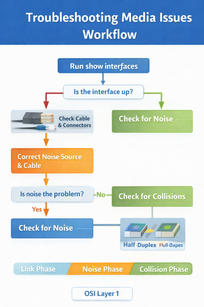
How It Works
- Run
show interfacesto check whether the interface is operational. - If the interface is down, inspect the cable and connectors.
- If the interface is up, use
show interfacesagain to look for excessive noise. - Excessive noise is often indicated by rising CRC errors.
- If noise is present:
- remove the noise source
- verify cable length
- confirm correct cable category
- If noise is not the problem, check for excessive collisions.
- If collisions or late collisions are present, verify duplex settings on both ends.
Symptom of excessive noise
A key symptom is:
- CRC errors increasing while collisions remain constant
This is a classic CCNA troubleshooting pattern.
OSI Layer(s)
- Layer 1: cable condition, noise, media type
- Layer 2: collisions, late collisions, duplex mismatch
Protocols Involved
- Ethernet
- CRC checking within Ethernet frame validation
Relevant Cisco Commands
show interfaces
Primary command for checking:- link status
- CRC errors
- collisions
- speed
- duplex
Real-World Examples
- In a branch office, a damaged patch cable causes the interface to remain down.
- In a manufacturing floor, electrical noise increases CRC errors on a copper run.
- In a small office, a duplex mismatch creates collisions and poor throughput.
Basic Troubleshooting
- Start with interface state: up/down
- Then evaluate noise and CRC
- Then evaluate collisions and duplex
- Correct physical causes before changing software settings
Important Points
show interfacesis the main command for media troubleshooting.- Rising CRC with stable collision count suggests noise.
- Late collisions commonly point to duplex problems.
- Use a process, not guesswork.
Key Idea
A disciplined media workflow begins with link status, then checks for noise, then checks for collisions. The command
show interfacesprovides most of the required evidence.
Port Issues
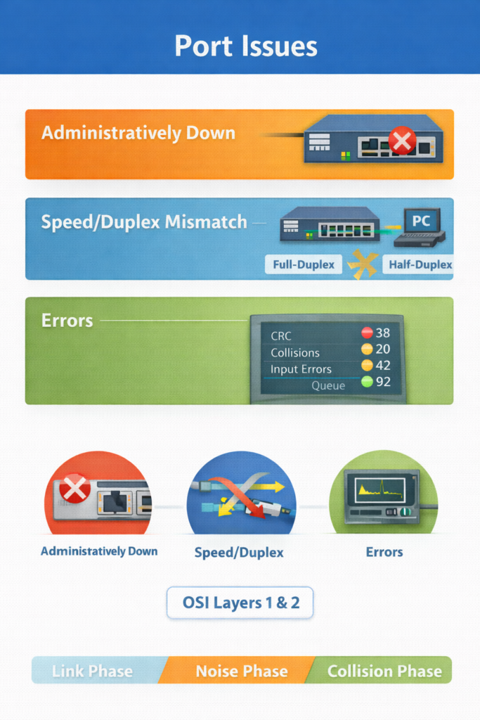
Definition
A port issue is a problem affecting the operational behavior of a switch interface, often visible as no connectivity, unstable connectivity, or very poor performance.
How It Works
- A switch port must be enabled, physically connected, and correctly configured.
- Even if cabling is good, speed or duplex mismatch can create major performance problems.
- Common visible symptoms include:
- users unable to connect
- slow throughput
- intermittent link behavior
- Faulty media or NICs may also contribute, but many port issues are configuration related.
OSI Layer(s)
- Layer 1: link state, cabling, transceivers
- Layer 2: speed, duplex, collisions
Protocols Involved
- Ethernet
- Auto-negotiation under IEEE Ethernet standards for speed/duplex exchange
Relevant Cisco Commands
show interfacesduplex {full | half | auto}
Real-World Examples
- A server port is hard-coded to full-duplex while the switch uses auto-negotiation.
- A user access port is administratively shut down and the PC has no link.
Basic Troubleshooting
- Confirm the port is not administratively down.
- Verify speed and duplex on both ends.
- Replace known-good cable if necessary.
- Check for interface counters indicating errors.
Important Points
- Many port problems are configuration issues, not hardware failure.
- Duplex and speed mismatch are common causes.
- Interface shutdown state is an easy but important check.
- Visible user complaints often begin at the switch port.
Key Idea
Port problems often appear simple but may involve both physical and data-link causes. Checking interface status, speed, and duplex is usually the fastest path to the root cause.
Duplex and Speed-Related Issues
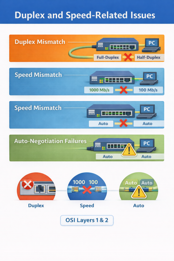
Definition
A duplex mismatch occurs when one end of a link uses full-duplex and the other uses half-duplex. A speed mismatch occurs when the two ends of a link are set to different Ethernet speeds. Auto-negotiation is the Ethernet mechanism used by devices to agree on speed and duplex settings.
How It Works
Duplex
- In full-duplex, both sides can transmit and receive at the same time.
- In half-duplex, devices share transmission time and collisions can occur.
- If one end is full-duplex and the other is half-duplex:
- performance becomes very poor
- collisions and frame errors may rise
- connectivity may become intermittent
Speed
- Both ends of an Ethernet link must use a compatible speed.
- If they do not, the link may fail or behave incorrectly.
- Auto-negotiation usually prevents this, but failures are still possible.
Cases described in the text
- Full on one side, half on the other → mismatch
- Full on one side, auto on the other → possible mismatch if negotiation fails
- Half on one side, auto on the other → both may end at half, no mismatch
- Auto on both sides → may succeed, or both may fall back
- One side fixed speed, other side different speed → mismatch
CCNA-related standard
The IEEE 802.3ab Gigabit Ethernet standard requires auto-negotiation for speed and duplex.
OSI Layer(s)
- Layer 2: Ethernet duplex operation and frame transmission
- Layer 1: physical link speed and signaling
Protocols Involved
- Ethernet
- IEEE 802.3ab: Gigabit Ethernet standard
- CDP: can report duplex mismatch between Cisco devices
Relevant Cisco Commands
show interfaces FastEthernet0/1
Displays the negotiated or configured speed and duplex.duplex full
Sets the interface to full-duplex.duplex half
Sets the interface to half-duplex.duplex auto
Allows auto-negotiation of duplex mode.- Depending on platform, speed can also be set manually with the interface speed command.
Real-World Examples
- In an enterprise network, a server NIC is hard-coded to full-duplex while the switch port falls back to half-duplex.
- In a campus core, two network devices are manually configured with inconsistent speed values.
- In a branch office, a router-to-switch link performs poorly because one side uses fixed settings and the other uses auto-negotiation.
Basic Troubleshooting
- Check speed and duplex on both ends.
- Prefer full-duplex on point-to-point Ethernet links.
- Use auto-negotiation for noncritical endpoints.
- Manually set both sides on critical infrastructure or server links when required.
- Review logs for CDP duplex mismatch messages.
Important Points
- Duplex mismatch causes very slow and unstable connectivity.
- Speed mismatch can prevent proper Ethernet communication.
- Auto-negotiation is standard practice for many access links.
- Gigabit Ethernet requires auto-negotiation under IEEE 802.3ab.
Key Idea
Duplex and speed mismatches are among the most common Ethernet port problems.
show interfacesis the primary command for identifying them, and both sides of the link must agree on compatible settings.
Troubleshooting Process for Duplex and Speed-Related Issues
Definition
This is the operational procedure used to isolate and correct speed and duplex mismatches between a switch and another device.
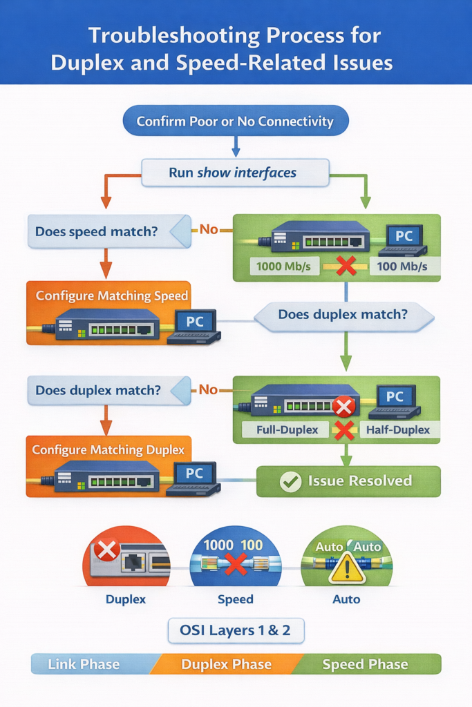
How It Works
- Confirm the link has poor or no connectivity.
- Run
show interfaceson the switch interface. - Check whether the interface speed matches the device on the far end.
- If a speed mismatch exists, configure the same speed on both sides.
- Check whether the interface duplex matches the far end.
- If a duplex mismatch exists, configure matching duplex settings on both sides.
- Prefer full-duplex on point-to-point Ethernet links.
- Use auto-negotiation for noncritical endpoints unless a manual setting is required.
- For critical links such as switch-to-switch, switch-to-router, or server links, manual matching settings may be appropriate.
OSI Layer(s)
- Layer 1: speed and physical signaling
- Layer 2: duplex operation, collisions, link efficiency
Protocols Involved
- Ethernet
- CDP
Relevant Cisco Commands
show interfaces
Verifies speed mismatch and duplex mismatch symptoms.show interfaces FastEthernet0/1
Example of interface-specific troubleshooting.duplex full | half | auto
Configures duplex mode.
Example from the text
The output line:
Full-duplex, 100Mb/s, media type is 10/100BaseTXshows the currently active duplex and speed values.
CDP mismatch example
%CDP-4-DUPLEX_MISMATCH: duplex mismatch discovered on FastEthernet0/1 (not half duplex)This message indicates that CDP detected a duplex mismatch on the link.
Real-World Examples
- A router uplink to a switch shows poor performance because one side is auto and the other is fixed.
- A server connection to a switch experiences low throughput until both ends are manually set to full-duplex and the same speed.
Basic Troubleshooting
- Verify interface counters and link state.
- Check logs for CDP duplex mismatch notifications.
- Compare settings on both ends, not only one side.
- Standardize settings across infrastructure links.
Important Points
- Point-to-point Ethernet links should normally be full-duplex.
show interfacesis the main verification command.- CDP can help identify mismatch problems.
- Critical links often require manual consistency on both ends.
Key Idea
Speed and duplex troubleshooting depends on comparing both sides of the link and correcting any mismatch. Cisco devices can provide direct evidence through
show interfacesand CDP log messages.
Troubleshooting Physical Connectivity Issue
Definition
A physical connectivity issue is any failure related to hardware connection, media, transceivers, or interface state that prevents normal network communication.
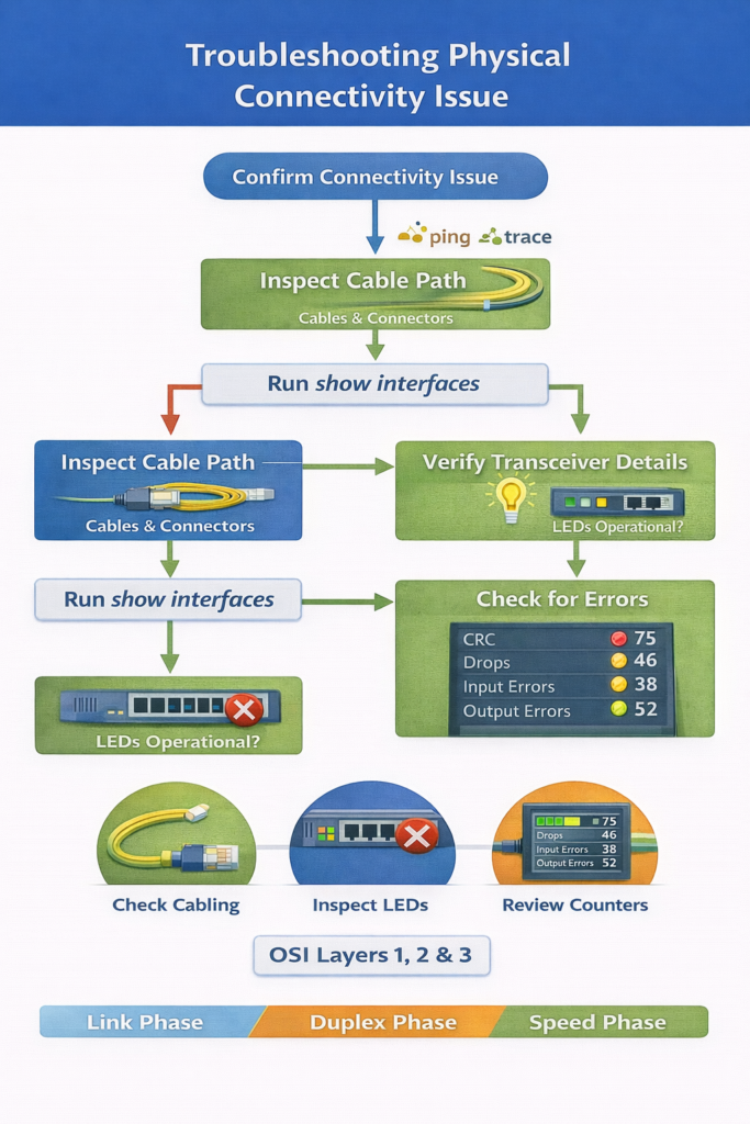
How It Works
- After using
pingandtracerouteto confirm a connectivity problem exists, inspect the physical path. - Check cables, connectors, and port LEDs.
- Verify the interface status using
show interfaces. - For fiber ports, verify:
- SFP or SFP+ type
- supported speed
- wavelength match
- SMF or MMF compatibility
- Review interface statistics for:
- input queue drops
- output queue drops
- input errors
- output errors
- collisions
- CRC errors
Important error meanings
- Input queue drops: traffic delivered faster than the device can process
- Output queue drops: packets dropped because the interface is congested
- Input errors: receive-side frame problems such as CRC
- Output errors: transmit-side problems such as collisions
CCNA point
A high collision count in modern switched Ethernet commonly indicates a duplex mismatch.
OSI Layer(s)
- Layer 1: cables, optics, LEDs, interface electrical/optical state
- Layer 2: CRC, collisions, Ethernet transmission errors
- Layer 3:
pingandtracerouteused to locate the issue
Protocols Involved
- ICMP: used by
ping - IP: used by
traceroute - Ethernet
- SFP/SFP+ optics are hardware standards rather than protocols, but they directly affect Layer 1 operation
Relevant Cisco Commands
ping
Confirms Layer 3 connectivity.traceroute
Helps isolate where connectivity stops.show interfaces
Verifies physical and data-link status.
Real-World Examples
- In a branch office, a patch cable is loose and the port LED is off.
- In a data center, a 1310 nm optic is incorrectly paired with an 850 nm optic, so the link never forms.
- In a campus distribution switch, persistent output drops indicate congestion and QoS may be required.
Basic Troubleshooting
- Physically inspect both ends of the link.
- Check port LEDs first.
- Confirm transceiver type, wavelength, and fiber mode.
- Review error counters over time, not just once.
- Correlate queue drops with traffic load and CPU behavior.
Important Points
- Always check physical connectivity before advanced troubleshooting.
- Port LEDs provide immediate link-state information.
- SFP/SFP+ type, wavelength, and fiber mode must match.
- Collision and CRC counters are key evidence.
Key Idea
Physical troubleshooting begins with simple checks such as cable seating, LEDs, and interface state. Accurate interpretation of
show interfacesstatistics is essential for identifying whether the problem is media, congestion, or duplex-related.
Speed and Duplex Settings for End-Device NIC and Switch Connections
Definition
This section is a practical troubleshooting example showing how to identify and fix a connectivity problem between switches and an end device by checking interface status and restoring an administratively disabled port. A NIC (Network Interface Card) is the hardware interface that connects an end device to the Ethernet network.
How It Works
Step 1: Test Layer 3 connectivity
SW1 pings PC2 at 10.10.1.20 and receives 0 percent success.
This indicates:
- no IP connectivity at Layer 3
- the cause may still be Layer 1 or Layer 2
Step 2: Check the switch port on SW2
The command:
SW2#show interfaces Ethernet0/2shows:
Ethernet0/2 is administratively down, line protocol is down (disabled)This means:
- the interface is shut down in configuration
- the port cannot forward traffic
Step 3: Fix the issue
Enable the interface:
SW2(config)#interface Ethernet 0/2
SW2(config-if)#no shutdown
no shutdown administratively enables the interface.
After that, the interface becomes:
Ethernet0/2 is up, line protocol is up (connected)Then SW1 can ping PC2 successfully.
Step 4: Save the configuration
Use:
SW2#copy running-config startup-configThis saves the current running configuration so the fix survives a reboot.
Note about Cisco IOL
In Cisco IOL virtual environments, interface status behavior may differ from physical devices. On real hardware, shutting down one side typically causes the connected side to show down/down. In Cisco IOL, behavior may differ due to virtualization limits.
OSI Layer(s)
- Layer 1: interface physical state
- Layer 2: switch port activation and Ethernet operation
- Layer 3: ping test confirms restored IP reachability
Protocols Involved
- ICMP: used by ping
- IP: destination addressing
- Ethernet: local link forwarding
Relevant Cisco Commands
ping 10.10.1.20
Tests Layer 3 reachability to PC2.show interfaces Ethernet0/2
Displays whether the port is up, down, or administratively down.configure terminal
Enters global configuration mode.interface Ethernet 0/2
Enters interface configuration mode for the target port.no shutdown
Enables a disabled interface.copy running-config startup-config
Saves the active configuration to NVRAM.
Real-World Examples
- In an enterprise access layer, a user cannot work because the switch port assigned to the desk is administratively shut down.
- In a lab environment, a port remains disabled after testing and users lose connectivity until it is re-enabled.
Basic Troubleshooting
- Start with
pingto verify reachability. - Move to
show interfacesto check the specific access port. - If the port is administratively down, enable it.
- Re-test reachability after the fix.
- Save the configuration so the issue does not return after reboot.
Important Points
- An administratively down interface is disabled by configuration.
show interfacesreveals the exact link state.no shutdownrestores interface operation.- Always save the configuration after fixing the issue.
Key Idea
This example shows that a Layer 3 failure may actually be caused by a simple Layer 1/Layer 2 issue: a shut down switch port. The correct process is verify, fix, test, and save.
CCNA Study Sheet
- Core concept summary
- Switch problems commonly occur at Layer 1 and Layer 2.
- Physical media faults, duplex mismatch, and speed mismatch are common causes of user connectivity problems.
show interfacesis the primary verification command.
- Key protocols involved
- Ethernet: physical and data-link communication
- IP: management and end-to-end reachability
- ICMP: ping testing
- CDP: Cisco-to-Cisco neighbor information and mismatch detection
- IEEE 802.3ab: Gigabit Ethernet auto-negotiation standard
- OSI layer reference
- Layer 1: cables, connectors, optics, EMI, LEDs, transceivers
- Layer 2: frames, MAC addresses, CRC, collisions, duplex
- Layer 3: ping, traceroute, management IP testing
- Commands to remember
show interfacesshow interface fa0/1pingtracerouteduplex fullduplex halfduplex autono shutdowncopy running-config startup-config
- Key exam points
- CRC errors increasing with stable collisions suggests noise.
- Late collisions should not occur in a well-designed Ethernet network.
- High collision count on switched Ethernet often indicates duplex mismatch.
- Point-to-point Ethernet links should normally be full-duplex.
- Gigabit Ethernet uses auto-negotiation by standard.
- Fiber links require matching optics, wavelength, and fiber type.
Summary
Switch troubleshooting requires accurate identification of the OSI layer where the failure begins. Copper issues commonly involve damaged cabling, EMI, CRC errors, and duplex-related collisions. Fiber issues commonly involve bend loss, splice loss, dirty connectors, and incorrect optical components. The most important Cisco command for investigating these conditions is show interfaces, which reveals link state, speed, duplex, CRC counts, collisions, queue drops, and other key counters.
Duplex and speed mismatches remain major causes of poor Ethernet performance. A duplex mismatch typically results in slow throughput, intermittent connectivity, and collision-related errors. Physical troubleshooting must also include port LEDs, cable checks, SFP/SFP+ verification, wavelength matching, and interface statistics. In practical troubleshooting, always verify the interface state first, correct the physical or configuration issue, confirm connectivity with ping, and save the configuration when needed.
LAB: Packet Tracer Lab – Troubleshooting Switch Port and Media Problems[Return to CCNA Study Hub] — Next Stop: [Section 3 | Fixing Port Duplex and IPv4 Addressing Problems]