
The Engineer’s Troubleshooting Toolkit
Troubleshooting is a fundamental skill for network administrators and engineers. When a network issue occurs, administrators must use diagnostic commands and tools to verify device operation, analyze network behavior, and isolate the source of the problem. Network devices and operating systems generate detailed command outputs that provide valuable operational information about interfaces, routing processes, protocols, and connectivity status.
One of the key challenges in troubleshooting is interpreting these outputs and identifying the information relevant to the issue being investigated. Because command outputs can contain large amounts of data, administrators must know how to efficiently analyze and filter the information to focus on specific details.
Cisco IOS includes several verification and troubleshooting commands that help administrators monitor device status and network performance. Additionally, Microsoft Windows network utilities can be used to test connectivity and validate communication between hosts. By combining these tools, administrators can systematically identify and resolve network problems.
Logging
Definition
Logging is a mechanism used by network devices to record system events, status changes, and operational messages. These messages help administrators monitor device activity and troubleshoot network issues.
How It Works
- Network devices generate system messages when events occur (for example, interface state changes or configuration changes).
- These messages are sent to an internal operating system process responsible for handling logs.
- The logging process sends messages to configured destinations such as:
- Console
- Terminal monitor sessions
- Memory buffer
- External syslog servers
- Each message has a severity level that indicates how critical the event is.
- Administrators review logs to determine when events occurred and identify problems.
In Cisco devices, logging messages are automatically sent to the console by default.
Example command to view logs:
Cisco Command
show logging
This command displays system logging information including:
- Logged events
- Severity levels
- Logging destinations
- Timestamped messages
Example log entries:
%SYS-5-RESTART: System restarted
%LINK-3-UPDOWN: Interface Ethernet0/0 changed state to up
%LINEPROTO-5-UPDOWN: Line protocol changed state to up
These messages show events in chronological order.
OSI Layer(s)
Logging is not tied to a specific OSI layer.
It monitors events occurring across multiple layers including:
- Layer 1 – Physical (interface up/down)
- Layer 2 – Data Link (line protocol state)
- Layer 3 – Network (routing events)
Protocols Involved
Syslog
- A protocol used to send logging messages to centralized logging servers.
- Allows centralized monitoring of multiple network devices.
Relevant Cisco Commands
show logging
Displays device logging configuration and recorded log messages.
terminal monitor
Enables log messages to appear in remote terminal sessions (Telnet or SSH).
Real-World Examples
Enterprise network administrators commonly use logging to detect issues such as:
- Interface failures in a campus switch
- Router reboots in an ISP network
- Configuration changes in a data center router
- Security alerts on firewall devices
For example, if a switch port goes down repeatedly, logs help identify when and how often it happens.
Basic Troubleshooting
Common checks using logging:
- Verify whether an interface changed state.
- Identify system restarts or configuration changes.
- Detect packet errors or collisions.
Typical troubleshooting steps:
- Run
show logging. - Identify timestamps of events.
- Check severity levels of messages.
- Correlate events with network problems.
Important Points
- Logging records device events for troubleshooting.
- Logs include timestamps and severity levels.
- Logs are sent to console by default.
- Remote terminal sessions require
terminal monitorto display logs.
Key Idea
Logging allows network devices to record operational events and system messages. These logs help administrators monitor network behavior and troubleshoot connectivity or configuration issues.
CCNA Study Sheet
Core concept summary
Logging records device events and system activities.
Key protocols involved
Syslog
OSI layer reference
Multiple layers depending on event type.
Commands to remembershow logging
Key exam points
- Logs contain severity levels (0–7)
- Logs include timestamps
- Default logging destination is the console
Severity Levels (Network Troubleshooting)
| Level | Name | Description | Example |
|---|---|---|---|
| 0 | Emergency | System is unusable. | Entire network device crashed |
| 1 | Alert | Immediate action required. | Critical hardware failure |
| 2 | Critical | Critical condition affecting the system. | Interface failure on core router |
| 3 | Error | Error condition occurred. | Interface errors or link failure |
| 4 | Warning | Potential problem detected. | High CPU usage warning |
| 5 | Notification | Normal but significant event. | Interface status change |
| 6 | Informational | Informational message about normal operation. | Routing table update |
| 7 | Debugging | Detailed debugging information. | Debug output for troubleshooting |
Internet Control Message Protocol (ICMP)
Definition
ICMP (Internet Control Message Protocol) is a network layer protocol used to send error messages and operational information about IP packet delivery. It helps network devices report problems such as unreachable hosts or expired packets.
How It Works
- A device sends an IPv4 packet across the network.
- Routers forward the packet toward its destination.
- If an error occurs during transmission, a router generates an ICMP message.
- The ICMP message is sent back to the source IP address.
Example situation:
- Each router decreases the TTL (Time To Live) value in an IPv4 packet.
- If TTL reaches 0, the router discards the packet.
- The router sends an ICMP Time Exceeded message to the sender.
ICMP is mainly used by diagnostic tools such as:
- ping
- traceroute
OSI Layer(s)
Layer 3 — Network Layer
ICMP operates directly with IP.
Protocols Involved
- ICMP: Used for error reporting and diagnostics.
- IP: ICMP messages are encapsulated inside IP packets.
Relevant Cisco Commands
ICMP itself is not configured with commands, but it is used by diagnostic commands:
ping
Tests connectivity between devices using ICMP Echo messages.
traceroute
Uses ICMP responses to discover the path packets take.
Real-World Examples
ICMP is used frequently in network diagnostics:
Enterprise network example:
- An administrator uses ping to check if a server is reachable.
ISP example:
- Engineers use traceroute to identify which router in a path is dropping packets.
Data center example:
- Monitoring systems use ICMP to detect server availability.
Basic Troubleshooting
Common ICMP-related issues:
- Host unreachable
- Time exceeded
- Network unreachable
Typical troubleshooting steps:
- Run ping to test connectivity.
- If ping fails, run traceroute.
- Identify which router returns ICMP errors.
Important Points
- ICMP is used for diagnostics and error reporting.
- ICMP messages are encapsulated inside IP packets.
- ICMP does not use TCP or UDP ports.
- ICMP operates at OSI Layer 3.
Key Idea
ICMP allows network devices to report errors and diagnostic information related to IP packet delivery. Tools like ping and traceroute rely on ICMP messages to test connectivity and identify network issues.
CCNA Study Sheet
Core concept summary
ICMP reports network errors and supports connectivity diagnostics.
Key protocols involved
ICMP, IP
OSI layer reference
Layer 3 (Network)
Commands to rememberpingtraceroute
Key exam points
- ICMP messages are encapsulated in IP
- ICMP has no port numbers
- Used by ping and traceroute
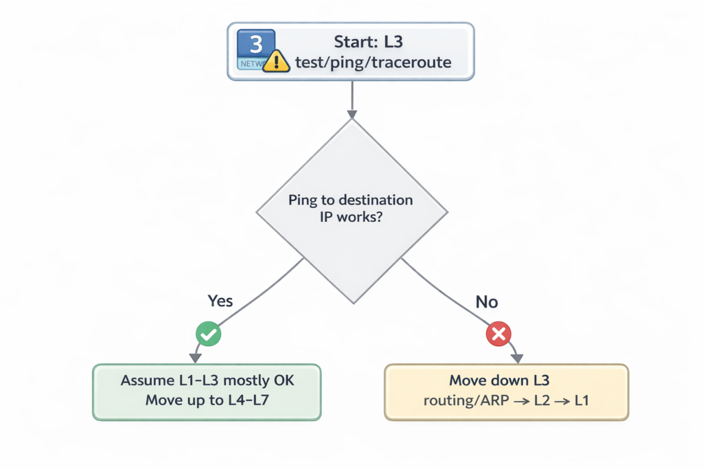
Verification of End-To-End IPv4 Connectivity
Definition
End-to-end connectivity verification involves testing whether two devices in a network can successfully communicate using IPv4.
How It Works
Administrators use diagnostic tools to confirm connectivity between devices and identify where communication fails.
Common tools include:
- ping
- traceroute
Telnet- SSH
- ARP table inspection
- interface configuration verification
OSI Layer(s)
Layer 3 — Network layer (IP connectivity)
Layer 4 — Transport layer (TCP connectivity tests)
Protocols Involved
- ICMP
- TCP
- ARP
- IP
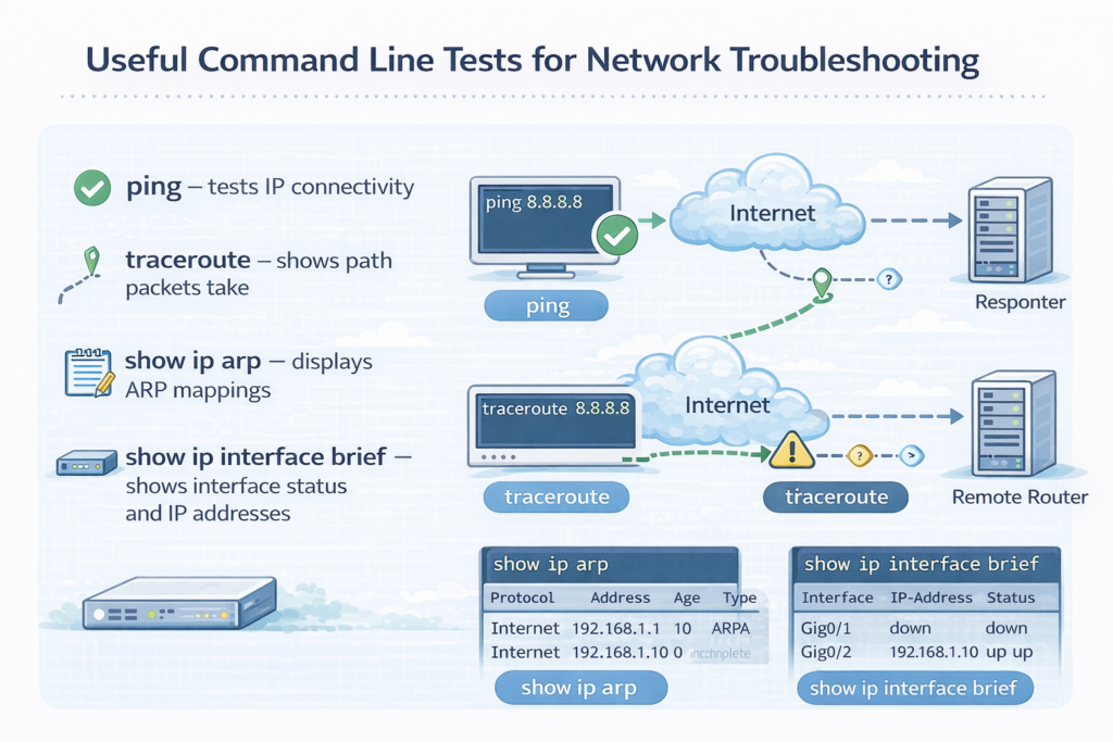
Relevant Cisco Commands
ping – tests IP connectivitytraceroute – shows path packets takeshow ip arp – displays ARP mappingsshow ip interface brief – shows interface status and IP addresses
Windows equivalents:
pingtracertarp -aipconfig /all
Real-World Examples
Enterprise network troubleshooting:
- Checking if a workstation can reach a gateway
- Verifying connectivity between branch routers
- Testing server reachability from a data center
Basic Troubleshooting
Typical process:
- Check interface status.
- Verify IP configuration.
- Ping the gateway.
- Use traceroute if ping fails.
- Check ARP table mappings.
Important Points
- Connectivity tests verify communication between devices.
- Different tools test different layers of the network.
- Troubleshooting often begins with ping.
Key Idea
End-to-end connectivity testing confirms whether two devices can communicate across the network. Tools like ping, traceroute, and ARP inspection help identify where communication failures occur.
CCNA Study Sheet
Core concept summary
Testing connectivity ensures devices can communicate over IPv4.
Key protocols involved
ICMP, TCP, ARP
OSI layer reference
Layer 3 and Layer 4
Commands to rememberpingtracerouteshow ip arpshow ip interface brief
Key exam points
- Ping tests basic connectivity
- Traceroute identifies path failures
- ARP verifies MAC resolution
Using ping
Definition
ping is a network diagnostic command that tests reachability between devices using ICMP Echo Request and Echo Reply messages.
How It Works
- The device sends an ICMP Echo Request packet to a destination.
- The destination device responds with an ICMP Echo Reply.
- The sender measures the round-trip time (RTT).
- The process repeats multiple times to calculate statistics.
Results indicate:
- Host availability
- Packet loss
- Network latency
Example command:
ping 10.10.50.1
Successful result:
!!!!!
Success rate is 100 percent
Failed result:
.....
Success rate is 0 percent
Symbols interpretation:
!reply received.timeout occurred
Extended ping allows additional parameters such as specifying a source address.
OSI Layer(s)
Layer 3 — Network Layer
Protocols Involved
ICMP
IP
Relevant Cisco Commands
ping
Tests IP connectivity.
Extended ping
ping
Allows custom parameters such as source address or packet size.
Real-World Examples
Network administrators use ping to:
- Verify a server is reachable
- Test connectivity between routers
- Confirm that a gateway is operational
- Check latency between data center networks
Basic Troubleshooting
If ping fails:
- Verify IP configuration.
- Check interface status.
- Verify routing tables.
- Confirm firewall rules are not blocking ICMP.
Important Points
- Ping uses ICMP Echo messages.
- It measures RTT and packet loss.
- It is the most common connectivity test.
- Extended ping allows advanced testing.
Key Idea
Ping tests whether a remote device can be reached over IP. It uses ICMP Echo messages to verify connectivity, measure latency, and detect packet loss.
CCNA Study Sheet
Core concept summary
Ping verifies device reachability using ICMP.
Key protocols involved
ICMP
OSI layer reference
Layer 3
Commands to rememberping
Key exam points
- Echo request and echo reply
- RTT measurement
- Success symbols
!and timeout.
Using traceroute (Cisco IOS) or tracert (Microsoft Windows)
Definition
Traceroute is a network diagnostic tool used to identify the path packets take from a source device to a destination device.
How It Works
- Traceroute sends packets with increasing TTL values.
- The first router decreases TTL to zero and discards the packet.
- The router sends an ICMP Time Exceeded message.
- The source records the router’s IP address.
- The process repeats with higher TTL values until the destination is reached.
Example:
traceroute 10.10.50.2
Output shows each router in the path.
OSI Layer(s)
Layer 3 — Network Layer
Protocols Involved
ICMP
UDP
IP
Relevant Cisco Commands
traceroute
Displays network path.
Extended traceroute
traceroute 10.10.50.2 source Loopback0
Windows equivalent:
tracert
Real-World Examples
Traceroute is used in:
Enterprise networks:
- Identify routing issues between sites.
ISPs:
- Determine which router is causing latency.
Data centers:
- Diagnose packet drops along network paths.
Basic Troubleshooting
Common traceroute problems:
- Timeouts (*)
- Routing loops
- Firewall blocking ICMP
Steps:
- Identify last responding router.
- Investigate routing configuration.
- Check access control lists.
Important Points
- Traceroute identifies each hop along a path.
- Uses TTL expiration to discover routers.
- Helps isolate network failures.
Key Idea
Traceroute determines the path packets take across a network by incrementing TTL values and analyzing ICMP responses from intermediate routers.
CCNA Study Sheet
Core concept summary
Traceroute maps the route packets follow.
Key protocols involved
ICMP, UDP
OSI layer reference
Layer 3
Commands to remembertraceroutetracert
Key exam points
- Uses increasing TTL values
- Reveals routers in the path
- Identifies routing failures
Using Telnet and SSH
Definition
Telnet and SSH (Secure Shell) are protocols used to remotely access network devices and manage them through command-line sessions.
How It Works
- A client initiates a connection to a remote device.
- The device accepts the session if authentication succeeds.
- A remote command-line interface is provided.
Telnet default port:
- TCP port 23
SSH default port:
- TCP port 22
SSH encrypts traffic, while Telnet sends data in plaintext.
OSI Layer(s)
Layer 7 — Application
Layer 4 — Transport (TCP)
Protocols Involved
Telnet
SSH
TCP
Relevant Cisco Commands
telnet <IP address>
Connects to a remote device.
ssh <IP address>
Starts an encrypted remote session.
Example:
telnet 10.10.50.2 80
This tests whether TCP port 80 (HTTP) is open.
Real-World Examples
Enterprise network administration:
- SSH used to configure routers and switches remotely.
Data center management:
- Secure CLI access to servers and network devices.
Basic Troubleshooting
Use Telnet to test port connectivity:
Example:
telnet 10.10.50.2 80
If the port is open, the connection succeeds.
Common issues:
- Closed TCP port
- Firewall blocking access
- Incorrect credentials
Important Points
Telnet uses TCP port 23.- SSH uses TCP port 22.
- SSH encrypts traffic.
- SSH is preferred for secure management.
Key Idea
Telnetand SSH provide remote command-line access to network devices. SSH is preferred because it encrypts communication and protects credentials.
CCNA Study Sheet
Core concept summaryTelnet and SSH allow remote device access.
Key protocols involvedTelnet, SSH, TCP
OSI layer reference
Layer 7 and Layer 4
Commands to remembertelnetssh
Key exam points
Telnetis insecure- SSH encrypts sessions
- Default ports: 23 and 22
Verify ARP table
Definition
ARP (Address Resolution Protocol) maps IPv4 addresses to MAC addresses within a local network.
How It Works
- A device needs to send a packet to another device on the same network.
- It knows the destination IPv4 address but not the MAC address.
- The device sends an ARP request broadcast.
- The target device replies with its MAC address.
- The mapping is stored in the ARP table.
OSI Layer(s)
Layer 2 — Data Link
Layer 3 — Network
Protocols Involved
ARP
Relevant Cisco Commands
show ip arp
Displays IPv4-to-MAC address mappings.
Real-World Examples
Enterprise networks:
- Switches and routers use ARP to forward packets to local devices.
Basic Troubleshooting
Check ARP table when:
- Devices cannot communicate locally
- Duplicate IP addresses exist
- MAC address conflicts occur
Important Points
- ARP resolves IPv4 to MAC addresses.
- ARP operates in local networks only.
- ARP entries are stored in ARP tables.
Key Idea
ARP allows devices to discover the MAC address associated with an IPv4 address on a local network, enabling proper frame delivery.
CCNA Study Sheet
Core concept summary
ARP maps IP addresses to MAC addresses.
Key protocols involved
ARP
OSI layer reference
Layer 2 and Layer 3
Commands to remembershow ip arp
Key exam points
- ARP request is broadcast
- ARP reply is unicast
Verify IPv4 address information
Definition
IPv4 address verification ensures that devices have correct network configuration including IP address, subnet mask, and default gateway.
How It Works
Administrators use commands to inspect interface configuration and verify correct IP parameters.
OSI Layer(s)
Layer 3 — Network Layer
Protocols Involved
IP
DNS
WINS (legacy Windows name resolution)
Relevant Cisco Commands
show ip interface brief
Displays:
- Interface status
- IPv4 address
- Protocol state
Windows commands:
ipconfig
Shows IPv4 address information.
ipconfig /all
Shows detailed network configuration including:
- DNS servers
- Default gateway
- Adapter details
Real-World Examples
Enterprise troubleshooting:
- Verify that a workstation received the correct IP address from DHCP.
- Confirm that routers have correct interface IP addresses.
Basic Troubleshooting
Common checks:
- Verify IP address.
- Confirm subnet mask.
- Check default gateway.
- Ensure interface is up.
Important Points
- IP configuration must match network design.
- Incorrect IP addressing prevents communication.
- Commands help verify configuration quickly.
Key Idea
IPv4 verification ensures that network interfaces have correct IP configuration, which is necessary for devices to communicate across networks.
CCNA Study Sheet
Core concept summary
Verifying IPv4 configuration ensures correct network connectivity.
Key protocols involved
IP, DNS
OSI layer reference
Layer 3
Commands to remembershow ip interface briefipconfigipconfig /all
Key exam points
- Verify IP, mask, and gateway
- Check interface status
- Ensure correct DNS configuration
Reference tables
Table 1 — Cisco IOS ping Output Characters
| Character | Meaning (simple) |
|---|---|
! | Reply received (success) |
. | Timeout (no reply) |
U | Destination unreachable (ICMP unreachable received) |
Q | Source quench / too busy (rare/obsolete) |
M | Can’t fragment (MTU issue, often DF set) |
? | Unknown packet type |
& | Packet lifetime exceeded (TTL expired) |
Table 2 — Common ICMP Types for Troubleshooting
| ICMP Type | Name | Meaning (simple) |
|---|---|---|
| 8 | Echo Request | “Are you there?” (ping sends) |
| 0 | Echo Reply | “Yes, I’m here.” (ping reply) |
| 3 | Destination Unreachable | “I can’t reach it.” |
| 11 | Time Exceeded | “TTL hit 0” (used by traceroute) |
| 5 | Redirect | “Use a better gateway/path.” |
| 4 | Source Quench | “Slow down” (rare/obsolete) |
| 6 | Alternate Address | Alternative address info (rare) |
| 9 | Router Advertisement | Router announces itself |
| 10 | Router Solicitation | Host asks for routers |
Table 3 — ICMP Type 3 (Destination Unreachable) Codes
| Code | Meaning |
|---|---|
| 0 | Network unreachable |
| 1 | Host unreachable |
| 2 | Protocol unreachable |
| 3 | Port unreachable |
| 4 | Fragmentation needed (DF set) |
| 5 | Source route failed |
Table 4 — ICMP Type 11 (Time Exceeded) Codes
| Code | Meaning |
|---|---|
| 0 | TTL exceeded in transit |
| 1 | Fragment reassembly time exceeded |
Table 5 — Quick Memory Table (Most Important)
| Tool/Problem | ICMP Type(s) to remember |
|---|---|
| Ping | 8 → 0 |
| “Can’t reach destination” | 3 |
| Traceroute | 11 |
Summary
This chapter introduced fundamental troubleshooting tools used to monitor network behavior and verify IPv4 connectivity. Logging mechanisms allow administrators to track system events and operational changes on network devices. ICMP provides diagnostic and error-reporting capabilities that support utilities such as ping and traceroute, which are essential for testing reachability and identifying packet paths across the network.
Additionally, commands such as show ip arp, show ip interface brief, ipconfig, and arp -a help verify addressing and Layer 2–Layer 3 mappings. Remote access tools like Telnet and SSH allow administrators to test transport-layer connectivity and manage devices remotely, with SSH providing secure encrypted access.
Together, these tools form the foundation of a structured troubleshooting process that enables network administrators to identify, isolate, and resolve connectivity issues efficiently in IPv4 networks.
LAB: Packet Tracer Lab – Monitoring Interface Events with Cisco Logging[Return to CCNA Study Hub] — Next Stop: [Section 3 | Switch Port & Media Troubleshooting]