
INTRO
This lab is not pre-built. Build this entire lab in Packet Tracer. No templates ——you are responsible for the full topology and configuration. Prove it works by testing connectivity and validating every requirement. If you haven’t installed it yet or don’t know how to use Packet Tracer, go to: https://fromzerotoccna.com/packet-tracer/
1. LAB OBJECTIVES
Students will practice basic Cisco logging and interface event monitoring.
Objectives:
- Understand how Cisco devices generate log messages.
- Configure a router interface and observe operational events.
- Use Cisco IOS logging commands to review system messages.
- Identify link and protocol state changes using logs.
- Interpret severity levels in Cisco syslog messages.
2. DEVICE DETAILS
| Device | Role |
|---|---|
| R1 | Router |
| ACCESS-SW1 | Access Switch |
| Host-A | Client PC |
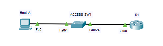
3. NETWORK TOPOLOGY
| Device A | Interface | Device B | Interface | Cable Type |
|---|---|---|---|---|
| Host-A | NIC | ACCESS-SW1 | Fa0/1 | Copper Straight-Through |
| ACCESS-SW1 | Fa0/24 | R1 | G0/0 | Copper Straight-Through |
4. TOPOLOGY DIAGRAM
5. IP ADDRESSING TABLE
| Device | Interface | IP Address | Subnet Mask | Default Gateway |
|---|---|---|---|---|
| R1 | G0/0 | 192.168.1.1 | 255.255.255.0 | N/A |
| Host-A | NIC | 192.168.1.10 | 255.255.255.0 | 192.168.1.1 |
6. DEVICE CONFIGURATION
R1 Configuration
enable
configure terminal

hostname R1

interface g0/0
ip address 192.168.1.1 255.255.255.0
no shutdown
exit

end
write memory
PC Configuration (Host-A)
Configure manually in Packet Tracer.
IP Address: 192.168.1.10
Subnet Mask: 255.255.255.0
Default Gateway: 192.168.1.1
7. VERIFICATION
Verify connectivity between the PC and router.
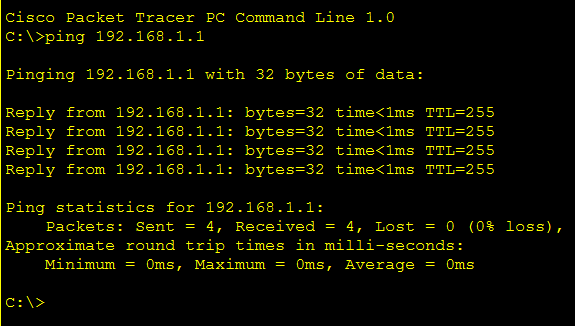
Test Connectivity
From the PC:
ping 192.168.1.1Expected result:
Successful replies confirming Layer-3 connectivity.
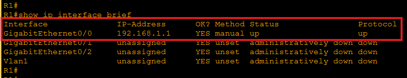
Verify Router Interfaces
show ip interface briefExpected output:
- GigabitEthernet0/0 should be up/up.
- The interface should display IP 192.168.1.1.
Verify Logging Messages
show loggingTypical output messages include:
%LINK-3-UPDOWN: Interface GigabitEthernet0/0, changed state to up %LINEPROTO-5-UPDOWN: Line protocol on Interface GigabitEthernet0/0, changed state to upExplanation:
| Field | Meaning |
|---|---|
| LINK | Physical interface status |
| LINEPROTO | Layer-2/Layer-3 protocol state |
| Severity Level | Indicates importance of the event |
Severity numbers range from 0 (Emergency) to 7 (Debugging).
8. GENERATING INTERFACE EVENTS
Administrators often generate or observe logs when interfaces change state.
Enter interface configuration mode:
configure terminal
interface g0/0
Shut down the interface:
shutdown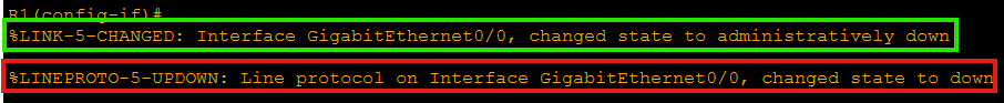
Wait a few seconds and bring it back up:
no shutdown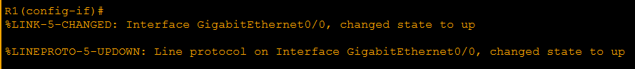
Exit configuration mode and check logs again:
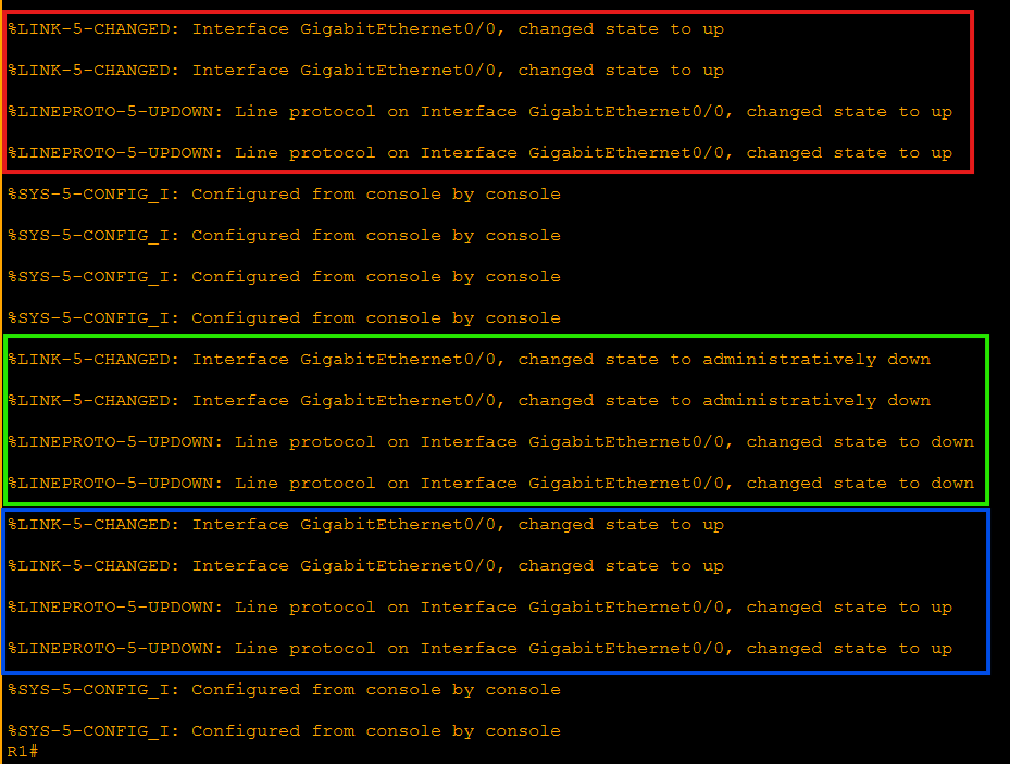
show loggingExpected new messages:
%LINK-5-CHANGED: Interface GigabitEthernet0/0, changed state to administratively down %LINK-3-UPDOWN: Interface GigabitEthernet0/0, changed state to down %LINEPROTO-5-UPDOWN: Line protocol changed state to downThese messages confirm that Cisco IOS records interface events automatically.
9. TROUBLESHOOTING CHALLENGE
Scenario
A network administrator reports that Host-A cannot reach the router. The network topology is already deployed, but users report intermittent connectivity. Your task is to determine why communication between Host-A and R1 fails. Students should investigate using the following commands:
ping
show ip interface brief
show logging
show running-configMonitoring Interface Events with Cisco Logging
Cisco Packet Tracer Simulation
Download the Lab File
This lab was created in Cisco Packet Tracer.
Download .PKT FileRequirements
- Cisco Packet Tracer installed
- Download the .pkt file
- Open the file in Packet Tracer
Lab Objectives
- Configure IP addressing
- Connect routers and switches
- Test connectivity with ping
- Analyze the topology
Focus on:
- Interface operational status
- Logging events
- IP configuration
- Link state changes
Do not assume the configuration is correct. Verify every step.
10. INSTRUCTOR NOTES
The lab contains intentional configuration issues. Students must identify and correct them.
Problem 1 — Interface Shutdown
Interface:
GigabitEthernet0/0Problem:
The interface may be administratively down.
Incorrect state example:
GigabitEthernet0/0 administratively downFix:
configure terminal
interface g0/0
no shutdown
Problem 2 — Incorrect Default Gateway on Host
Host-A may have the wrong gateway.
Incorrect:
192.168.1.254Correct configuration:
Default Gateway: 192.168.1.1Problem 3 — Logging Not Reviewed
Students must check logs to identify events.
Key command:
show loggingExpected message indicating interface issue:
%LINK-3-UPDOWN: Interface GigabitEthernet0/0, changed state to downThis message indicates that the physical interface lost connectivity.
NOTE: This lab introduces the foundational concepts of Cisco logging, syslog severity levels, and interface state monitoring, which are essential troubleshooting skills for CCNA-level network engineers.